


As electronic products become smaller, lighter, and more complex, traditional rigid circuit boards do not always fit the design. Flexible printed circuit boards, or flex PCBs, offer a practical solution by allowing circuits to bend, fold, and fit into compact or irregular spaces. Their value goes beyond flexibility. The right structure and materials can reduce weight, simplify assembly, and offer greater freedom in product design.
Realizing these benefits, however, depends on careful design and reliable manufacturing at every stage. With comprehensive flexible PCB manufacturing capabilities, PCBgogo helps turn complex designs into durable, production-ready circuits that meet real-world performance requirements. Let's take a closer look at what makes flexible PCBs unique and how PCBgogo supports each project from concept to finished board.
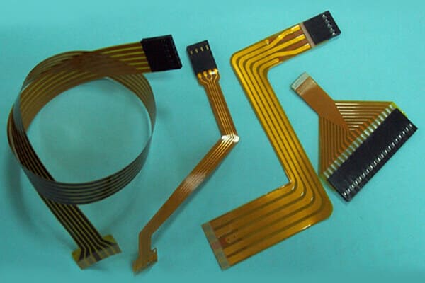
A flexible PCB, also known as a flex PCB or flex circuit, is a printed circuit board made with thin, bendable insulating materials such as polyimide. Unlike rigid PCBs, it can bend, fold, or conform to the shape of a product while maintaining reliable electrical connections. Flexible PCBs are widely used in modern electronic devices, including smartphones, wearables, medical equipment, automotive electronics, and other products where space, weight, or movement is an important design consideration.
Key characteristics of flexible PCBs include:
Flexible Construction: fits into curved, narrow, or irregular spaces.
Thin and Lightweight: helps reduce product size and overall weight.
Reliable Connections: replaces bulky wiring and reduces the number of connectors.
Movement Resistance: can support vibration or repeated motion when properly designed.
Design Freedom: allows components and circuits to be arranged more efficiently inside compact devices.
To take full advantage of a flexible PCB, flexibility needs to be considered from the beginning of the design process. A flex circuit should not be treated as a rigid PCB that simply bends. Its materials, copper layout, bend areas, and component placement must work together to prevent stress and maintain reliable performance throughout the product's life.
Important design considerations include:
Bend Radius: avoid sharp folds and allow enough space for the circuit to bend without damaging the copper or substrate.
Trace Routing: route traces smoothly through bend areas and avoid sharp corners that may create stress points.
Component and Via Placement: keep components, vias, and solder joints away from areas that will bend or move.
Layer Structure: choose the number of layers, copper thickness, coverlay, and base material according to the electrical and mechanical requirements.
Local Reinforcement: use stiffeners beneath connectors, contact fingers, or component areas that need additional support.
Manufacturability: include fabrication tolerances early and review the design before production to reduce avoidable manufacturing issues.
Even the best flex PCB design depends on precise and well-controlled manufacturing. With advanced production equipment, strict process control, and the ability to handle demanding flex constructions, PCBgogo turns complex designs into reliable, production-ready boards. Next, let's explore the flexible PCB capabilities that make this possible.
| No. | Process Capability Parameter | Specification |
|---|---|---|
| 1 | PCB Type | Flexible PCB |
| 2 | Quality Grade | Standard IPC 2 / Standard IPC 3 |
| 3 | Material | PI, PET |
| 4 | Layers | 1-12 Layers |
| 5 | Board Size Tolerance | ± 0.1 mm |
| 6 | FPC Thickness | 0.06-0.7 mm |
| 7 | FPC Thickness Tolerance | FPC Thickness ≤ 0.3mm: ±0.03mm FPC Thickness 0.3-1.0mm: ±0.1mm FPC Thickness > 0.3mm: ±10%~15% |
| 8 | Copper Thickness | 0.33-2.0 OZ |
| 9 | Hole Diameter | 0.1-6.5 mm |
| 10 | Diameter Tolerance | ±0.08 mm |
| 11 | Minimum Laser Hole Diameter | 0.1 mm |
| 12 | Minimum Trace Width/Spacing | Single/Double-layer: 2/2 mil Multilayer: 3/3 mil |
| 13 | BGA Pad Diameter | ≥ 6 mil |
| 14 | BGA Pad Tolerance | Prototype limit: Pad tolerance ±0.05mm Mass-production limit: ±1.5mil (Pad ≤10mil); ±10% (Pad >10mil) |
| 15 | Minimum Spacing for Gold Fingers | ≥ 5 mil |
| 16 | Coverlay | Yellow, White, Black, Transparent |
| 17 | Coverlay Opening Size | ≥0.6*0.6 mm |
| 18 | Minimum Solder Bridge Width | Base copper ≤1oz: 4-6mil Base copper 2-4oz: 20mil; 8mil |
| 19 | Min Spacing from Silkscreen to Soldering Pad | ≥ 0.2 mm |
| 20 | Character Line Width | ≥ 0.1 mm |
| 21 | Character Height | ≥ 1 mm |
| 22 | Surface Finish | ENIG, OSP, Immersion Tin, Chemical Silver |
| 23 | Impedance Tolerance | Single-ended: ±5Ω (≤50Ω), ±10% (>50Ω); tightest achievable tolerance: ±5% (≥50Ω) Differential: ±5Ω (≤50Ω), ±10% (>50Ω); tightest achievable tolerance: ±5% |
| 24 | Stiffener Material | PI, FR-4, Aluminum, Stainless Steel Stiffener, Copper |
| 25 | Stiffener Thickness | 0.1-1.6 mm |
| 26 | Other Options | 3M Tape, EMI Shielding Film |
PCBgogo - Reliable, High-Quality PCB Manufacturing
Save time and money with an all-in-one solution for PCB fabrication, assembly, and parts. Reduce vendor coordination, avoid split shipments, and get consistent, reliable quality.
Get Free Quote >
These characteristics do more than help a circuit fit into a smaller space; they can also make the finished product easier to design, assemble, and maintain. By replacing multiple wires, cables, and connectors with a single integrated circuit, flexible PCBs create a cleaner internal layout and reduce potential connection failures. Although their initial manufacturing cost may be higher than that of rigid PCBs, the simpler assembly and lower component count can help reduce overall production complexity.
Simpler Assembly: reduces manual wiring and makes installation more efficient.
Fewer Connection Points: minimizes connectors and solder joints that may become potential failure points.
Efficient Use of Space: allows circuits to be routed around corners, hinges, and mechanical structures.
Reliable Performance: maintains stable connections in products exposed to vibration, movement, or repeated handling.
Lower System Complexity: integrates multiple interconnections into one circuit, making the product easier to design and maintain.
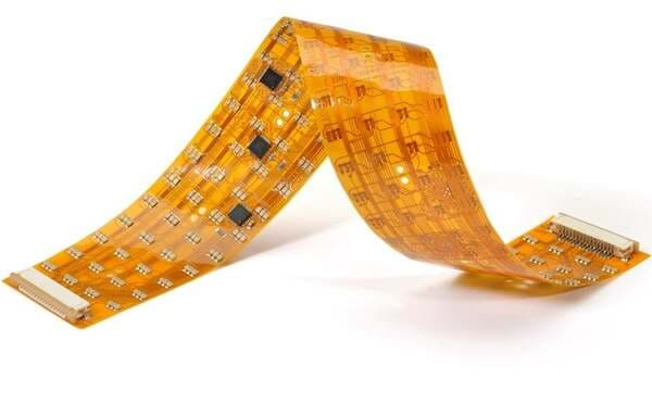
Because they can route electrical connections through narrow, curved, or moving spaces, flexible PCBs are used in products ranging from everyday electronics to highly specialized equipment. Their ability to reduce wiring, save space, and adapt to different shapes makes them especially valuable in the following applications:
Consumer Electronics: Flexible PCBs are widely used in smartphones, tablets, laptops, cameras, and wearable devices to connect components within slim, compact housings. They are also well suited to folding screens, hinges, and other areas where the circuit needs to move with the product.
Automotive Electronics: Modern vehicles use flex circuits in displays, lighting systems, cameras, sensors, and control modules. Their lightweight construction and resistance to vibration help them perform reliably in space-constrained automotive assemblies.
Medical Devices: Flexible PCBs can be found in hearing aids, patient-monitoring equipment, diagnostic devices, and wearable health products. Their small size allows designers to create lighter, more comfortable devices without sacrificing dependable electrical connections.
Aerospace and Defense Systems: Aircraft, satellites, and communication equipment benefit from flexible PCBs because they reduce cable weight and fit easily into tightly packed assemblies. Fewer connectors can also help improve reliability in systems exposed to vibration and demanding operating conditions.
Industrial Equipment and Robotics: Flex circuits are used in robotic arms, sensors, control systems, and other equipment with moving parts. When designed for dynamic bending, they can maintain stable connections through repeated motion.
LED Lighting: Flexible PCBs allow LEDs to be installed along curved surfaces and in areas where rigid boards would be difficult to mount. This makes them useful for automotive lighting, signage, architectural lighting, and compact illumination systems.
As products continue to become smaller, smarter, and more closely integrated, flexible PCBs will support an even wider range of designs and emerging technologies.

As electronic products continue to shrink and become more integrated, flexible PCB technology is moving toward finer circuits, higher interconnection density, thinner materials, and more reliable performance during repeated movement. Foldable electronics, wearable medical devices, electric vehicles, robotics, and smart sensors are also creating new demands for flex circuits that can carry more signals while fitting into increasingly limited spaces.
Flexible and rigid-flex PCBs are expected to replace more traditional wiring and connectors, giving engineers greater freedom to create compact, lightweight, and highly integrated products. Turning these ideas into reliable boards, however, will require precise manufacturing, careful material control, and close coordination between designers and manufacturers.
PCBgogo is ready to support the next generation of flexible PCB designs with advanced production capabilities and practical engineering support. Whether you are testing an early prototype or preparing a design for larger-scale production, contact PCBgogo to discuss your project and find the right flexible PCB solution for your application.
PCBgogo supports both flexible and rigid-flex PCBs. Its standard online quotation system covers 1-, 2-, 4-, and 6-layer flex PCB configurations, allowing customers to source anything from simple interconnect circuits to more complex multilayer designs. Special structures can also be reviewed according to project requirements.
Yes. PCBgogo offers FPC thickness options starting from 0.08 mm, with minimum trace and spacing down to 2/2 mil and minimum hole sizes down to 0.15 mm. These capabilities make it possible to produce compact flex circuits for products where space and routing density are critical.
PCBgogo uses polyimide as its standard flexible base material and provides several copper thickness options to meet different electrical and mechanical requirements. Available surface finishes include ENIG, OSP, immersion silver, and chemical tin, while gold fingers can be added for applications that require reliable connector interfaces.
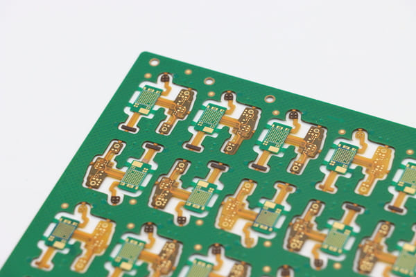
Yes. Customers can choose from PI, FR-4, and metal stiffeners to reinforce connectors, component areas, or mounting points. PCBgogo also supports several 3M and Tesa adhesive options, along with EMI shielding films for designs that require secure installation or improved protection against electromagnetic interference.
PCBgogo offers 100% electrical testing to verify circuit continuity and identify open or short circuits before shipment. Customers can also request work-file confirmation, giving them an opportunity to review the optimized production data before manufacturing begins. This additional review helps reduce misunderstandings and ensures the finished board matches the approved requirements.

 日本語
日本語
 한국어
한국어

