FR4 PCB is the most mainstream, versatile, and cost-effective substrate material for printed circuit boards, widely adopted in commercial, industrial, automotive, consumer electronics, and communication device manufacturing. As a reliable global FR4 PCB manufacturing supplier, PCBgogo delivers full-turnkey FR4 PCB fabrication services, covering prototype production, small-batch trial runs, and mass commercial production. With standardized production workflows, strict quality control systems, and flexible customization capabilities, we meet diverse custom FR4 PCB requirements for engineers, designers, and enterprises worldwide.
Our FR4 PCB manufacturing service supports single-sided, double-sided, and multi-layer FR4 PCBs with customizable specifications including board thickness, copper weight, thermal resistance (TG value), surface finishes, and precision tolerances. All FR4 circuit boards are fabricated with high-quality original FR4 substrate materials, featuring excellent insulation performance, mechanical stability, heat resistance, and chemical corrosion resistance.
Compared with ordinary PCB manufacturers, PCBgogo focuses on high-precision, high-reliability FR4 PCB fabrication, with multiple core strengths supporting high-quality product delivery:
We adopt standard industrial FR4 materials with multiple TG grade options (TG130-140, TG150-160, TG170-180) to match different application scenarios, ensuring stable thermal performance and avoiding delamination, warpage, and cracking during high-temperature soldering and device operation.
Covering mainstream FR4 PCB specifications including conventional and high-precision board thickness, line width/spacing, hole size, and impedance control. We support customized multi-layer stacking structures to meet the design needs of high-density interconnect (HDI) FR4 PCBs.
All FR4 PCB products are manufactured and inspected in accordance with IPC industry standards. We implement precise control over board thickness tolerance, hole position tolerance, and dimensional accuracy to ensure perfect compatibility with customer assembly processes.
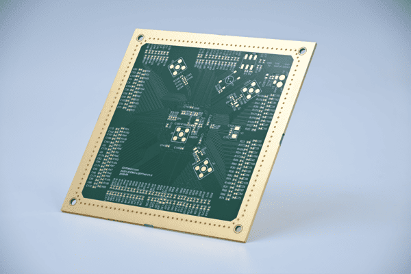
Provide multiple surface treatment processes such as HASL, lead-free HASL, ENIG, OSP, hard gold plating, and silver plating, effectively improving the solderability, oxidation resistance, and service life of FR4 circuit boards.
Integrate FR4 PCB proofing, batch production, component sourcing, and PCB assembly services. Customers only need to provide design files to complete the entire production process, saving procurement and time costs.
Our FR4 PCB manufacturing processes comply with international industry standards, with products meeting RoHS, UL, and other environmental and safety certifications, suitable for global market export and commercial application.
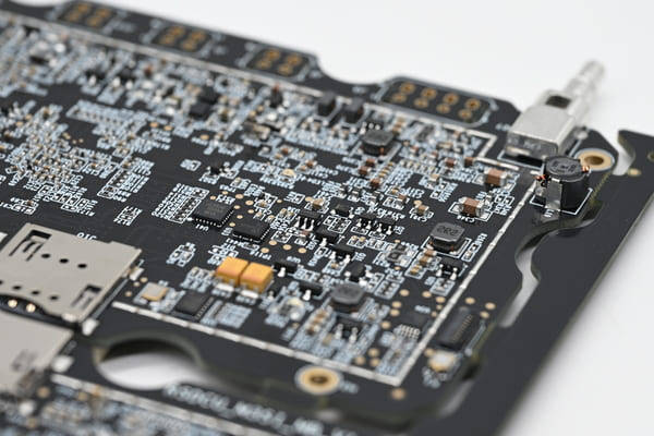
PCBgogo provides standardized and customized FR4 PCB fabrication solutions. The following detailed technical parameters cover all conventional and mainstream custom requirements for FR4 circuit boards. We strictly implement process standards in each production link to ensure product consistency and stability.
| No. | Item | Manufacturing Capabilities | Illustration |
|---|---|---|---|
| 1 | Material | FR-4 (Fiberglass) | For Rogers, Taconic, ARLON, and HDI boards, please contact PCBgogo for details. |
| 2 | Number of Layers | 1-40 Layers | Standard stackup for multilayer PCBs. |
| 3 | TG Grade | TG 130 TG 150 TG 170 S1000H TG 150 S1000-2M TG 170 | |
| 4 | Max PCB Size | ≤2 layers: 660*1143 mm ≥3 layers: 648*965 mm | 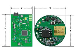
|
| 5 | Min PCB Size | 3*3 mm | |
| 6 | Board Size Tolerance | ± 0.1 mm(CNC routing) ± 0.4 mm(V-scoring) | |
| 7 | Surface Finish | HASL with lead, HASL lead-free, Immersion gold(ENIG), OSP, Hard gold, ENEPIG, Immersion silver (Ag), None | 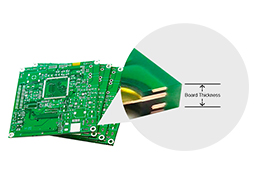
|
| 8 | Board Thickness | 0.2-7 mm (Note: Customized PCB thickness and Layer stackup are acceptable.) | |
| 9 | Board Thickness Tolerance | Thickness≥1.0 mm: ±10% Thickness<1.0 mm: ±0.1 mm | |
| 10 | Max Finished Outer Copper Thickness | 8 oz (Prototype) 6 oz (Batch) | 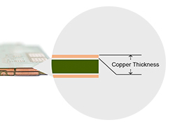
|
| 11 | Max Finished Inner Copper Thickness | 8 oz (Prototype) 4 oz (Batch) | |
| 12 | Outer layer Min track/spacing | ≥3 mil | 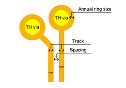
|
| 13 | Inner layer Min track/spacing | ≥4 mil | |
| 14 | Annular Ring Size | ≥0.13 mm | |
| 17 | BGA pad size | ≥0.15 mm | 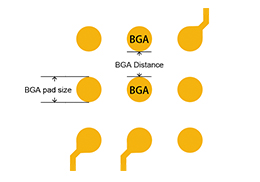
|
| 18 | BGA Distance | ≥0.1 mm | |
| 19 | Board Outlines | Track to Outline: ≥0.3 mm Trace to V-cut line: ≥0.4 mm | 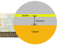
|
| 20 | Finished Hole Size Tolerance | ±0.08 mm | 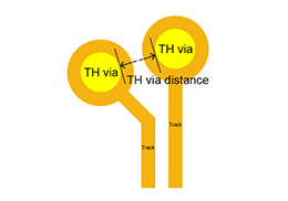
|
| 21 | Finished Hole Diameter(CNC) | 0.2 mm-6.3 mm
1. PCB Thickness=2.0mm, Min hole size is 0.3mm 2. PCB Thickness=2.4mm, Min hole size is 0.4mm 3. Copper Thickness=2OZ, Min hole size is 0.25mm 4. Copper Thickness=3OZ, Min hole size is 0.3mm | |
| 22 | TH Via Distance | Same nets: 0.15mm Different net: 0.25mm | |
| 23 | Plated Slot Size | ≥0.5mm
Note: L:W=2.5: 1 (Should be 2.5:1 or higher. If it is less than this, the holes may be misaligned.) If you can't draw a long hole in your design, you can draw a continuous round hole and it will be regarded as a long hole. Also, it is okay to draw the oblong hole in Profile Layer instead of Drilling Layer. | 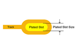
|
| 24 | Castellated Holes | ≥0.6 mm | 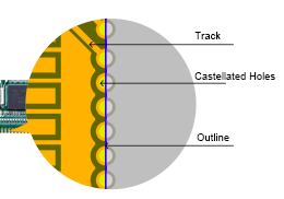
|
| 25 | Non-Plated Holes | ≥0.3 mm | 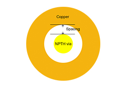
|
| 26 | Non-Plated Holes Diameter | ≥0.5mm | |
| 27 | Soldermask | Green, Red, Yellow, White, Black, Blue, Purple, Matte Green, Matte Black, None | 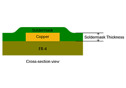
|
| 28 | Soldermask Thickness | 20~30um | |
| 29 | Soldermask Bridge | Green: ≥0.1mm Others: ≥0.15mm | 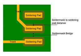
|
| 30 | Soldermask to soldering pad distance | ≥0.05mm | |
| 31 | Silkscreen | White, Black, Yellow, None | 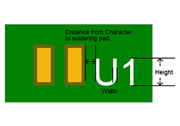
|
| 32 | Minimum Character Width(Legend) | ≥0.15mm
Note: Characters of less than 0.15mm wide will be too narrow to be identifiable. | |
| 33 | Minimum Character Height (Legend) | ≥0.75mm
Note: Characters of less than 0.8mm high will be too small to be recognizable. | |
| 34 | Character Width to Height Ratio (Legend) | 1: 5 (In PCB silkscreen legends processing, 1:5 is the most suitable ratio) | |
| 35 | Silkscreen to Soldering Pad Distance | ≥0.1mm | |
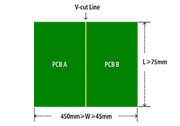
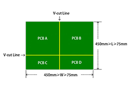
| 36 | V-cut Line | ≥70 mm
Note: PCB thickness≥0.6mm Details refer to the right side picture |
|
| 37 | V-cut Line Distance | ≥3.5mm | 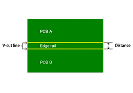
|
| 38 | Distance between Board to Board | ≥ 0.8 mm | 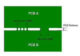
|
| 39 | Stamp-hole Width | ≥ 2.0 mm
Note: PCB size and thickness are subject to review by PCBGOGO. | |
| 40 | Tab-route Width | ≥ 1.6 mm
Note: PCB size and thickness are subject to review by PCBGOGO. | |
| 41 | Edge Rail | ≥3.5 mm
Note: If choosing a panel by PCBGOGO, we will add 5mm edge rails on both sides by default. | 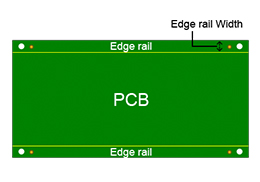
|
| 42 | Gold Finger | Bevelling Angle: 30~45° Depth: ≥1 mm Length: 45 mm~280 mm
Note: Board thickness ≥ 1.2 mm | 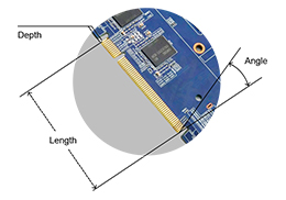
|
| 43 | Special Specification | Impedance control Custom Layer Stackup Interstitial Via Hole(IVH) Via in pad Via filled with resin Countersinks/Counterbores Carbon Mask Halogen-Free Z-axis milling Edge Plating Others |
PCBgogo - Reliable, High-Quality PCB Manufacturing
Save time and money with an all-in-one solution for PCB fabrication, assembly, and parts. Reduce vendor coordination, avoid split shipments, and get consistent, reliable quality.
Get Free Quote >
Benefiting from stable physical and chemical properties, FR4 substrates are the most widely used PCB material in the electronics industry. PCBgogo's custom FR4 PCB manufacturing services cover a full range of downstream electronic product fields, providing reliable circuit board support for various devices:
1. Consumer Electronics: Smart home devices, mobile peripherals, audio and video equipment, wearable electronic products, etc.
2. Industrial Control: Industrial motherboards, sensor modules, automation equipment, instrumentation and control circuit boards.
3. Automotive Electronics: Vehicle control modules, automotive communication systems, on-board entertainment equipment (adopting high TG FR4 materials for high-temperature resistance).
4. Communication Equipment: Router baseboards, signal transmission modules, communication terminal circuit boards with impedance control requirements.
5. Medical Electronics: Portable medical equipment, detection instrument circuit boards, meeting high stability and safety standards.
6. Aerospace & New Energy: Low-power control circuit boards, new energy charging and discharging management modules with high-reliability FR4 fabrication.
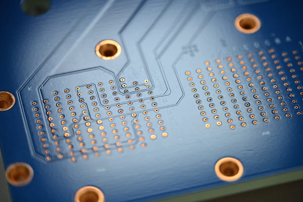
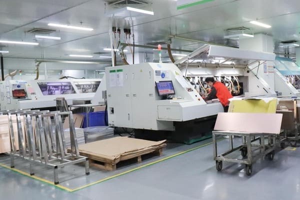
To ensure every batch of custom FR4 PCB meets customer design and quality standards, PCBgogo implements full-process quality monitoring from raw material incoming inspection to finished product delivery. We strictly screen original FR4 substrates, copper foil, solder mask ink, and other raw materials to eliminate unqualified materials from the source. In the production stage, we adopt automated exposure, etching, drilling, and laminating equipment to reduce manual errors and improve product consistency.
After production, all FR4 PCBs will undergo multiple inspections, including appearance inspection, dimensional tolerance detection, electrical performance testing, impedance testing, and thermal performance verification. For multi-layer FR4 PCBs, we conduct lamination quality inspection and inner layer circuit testing to avoid open circuits, short circuits, and hidden quality risks. Each batch of products is accompanied by complete inspection records, supporting quality traceability and after-sales guarantee.
As a professional PCB manufacturer with rich industry experience, PCBgogo focuses on providing high-cost-performance and high-reliability FR4 PCB fabrication services for global customers. We support fast PCB prototype proofing (24-48 hours quick turnaround) and stable mass production delivery, balancing quality, price, and delivery time perfectly. Whether you need simple single/double-sided FR4 PCBs or high-precision multi-layer customized FR4 circuit boards, we can provide targeted manufacturing solutions.
We support free file evaluation and technical consultation. Our professional engineering team will check your Gerber files, optimize design details for manufacturability, and provide reasonable production suggestions to help customers reduce production costs and improve product yield. Adhering to a factory direct sales mode without middlemen markup, we provide transparent pricing and stable after-sales service for all FR4 PCB manufacturing orders.
FR4 is a flame-retardant glass epoxy substrate with excellent insulation, mechanical strength, heat resistance and cost advantages. It is compatible with most electronic product design and assembly processes, making it the preferred material for civilian and industrial PCBs.
Conventional consumer electronics can choose TG130-140°C FR4 substrates; industrial and automotive electronic equipment with high-temperature working environments is suitable for TG170-180°C high-TG FR4 PCBs to prevent board warpage and delamination.
Yes. We provide one-stop FR4 PCB manufacturing and SMT assembly services, including component procurement, soldering, testing, and packaging, realizing one-stop delivery from design files to finished circuit boards.

 日本語
日本語
 한국어
한국어