
 日本語
日本語
 한국어
한국어

3-Axis vs 4-Axis vs 5-Axis CNC Machining Guide
QUICK ANSWER The practical difference in 3-axis vs 4-axis vs 5-axis CNC machining is tool access. Three-axis machines cut along X, Y and Z and are economical for parts reached from one direction. Four-axis machining adds rotary motion for cylindrical features and repeated work around a part. Five-axis machining adds a second rotary motion for compound angles and complex surfaces. Choose the lowest axis count that reaches every critical feature and holds the required relationships reliably.
Key Takeaways
Choose 3-axis machining for plates, brackets, pockets and other accessible prismatic geometry when extra setups do not threaten critical tolerances.
Choose 4-axis machining for indexed sides or features distributed around a cylinder, such as flats, slots and radial holes.
Choose 5-axis machining when compound angles, deep contoured surfaces, short-tool access or single-setup datum control justify more programming and machine time.
How CNC Machines Work
Computer numerical control machining removes material from a workpiece by following programmed toolpaths. A CAD model defines the geometry, CAM software converts machining intent into tool motion, and the machine controller coordinates feeds, spindle speed, tool changes and auxiliary functions. The result still depends on process planning. Workholding, cutter reach, material behavior, machine condition and inspection strategy can matter as much as the nominal axis count.
Core Components
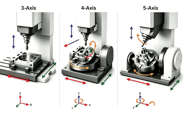
A machining center combines a rigid structure with servo-driven axes. The spindle rotates the tool, a fixture locates the workpiece, and coolant or air manages heat and chips. The controller coordinates motion, tool changes and auxiliary functions. X, Y and Z are linear movements. A, B and C describe rotation about those axes, although the table, spindle head or both may provide the physical motion.
More axes expand the angles from which a cutter can approach the part. They do not automatically make a machine more accurate. Any accuracy benefit usually comes from avoiding manual repositioning, keeping related features in one coordinate system and using shorter, more rigid tools.
What Is 3 Axis Machining
In 3-axis machining, the cutter moves along X, Y and Z while the workpiece stays in a fixed orientation during each operation. The machine can interpolate all three axes to create slopes and freeform surfaces, but the tool axis remains aligned in one direction. To machine another side, the operator normally reclamps or refixtures the part.
Advantages of 3 Axis Machining
Lower programming, setup and machine-hour cost for accessible geometry.
Rigid workholding and a large usable work envelope, especially for plates and block-shaped parts.
Broad tooling and CAM availability, with easier program verification and operator training.
Limitations of 3 Axis Machining
Features on several faces require additional setups. Each relocation introduces another chance for datum shift, angular error or inconsistent clamping. Deep walls and hidden features may also demand long tools, which can deflect, vibrate and leave visible tool marks. Undercuts and compound-angle features may be impossible without special fixtures or form tools.
Typical 3 Axis Applications
Common applications include plates, housings, simple molds, brackets, pockets, slots and drilling patterns. It suits prototypes and production parts when critical features share an accessible face and any remaining operations can be relocated reliably.
What Is 4 Axis Machining
A 4-axis CNC machine adds one rotary axis to X, Y and Z. In a common layout, an A-axis rotates the workpiece around X. Indexed 4-axis machining turns the part to a programmed angle and locks it before cutting. Continuous 4-axis machining moves the rotary and linear axes together, which supports wrapped profiles, helical paths and contours around a cylinder.
Advantages of 4 Axis Machining
Machines several sides without manual reclamping, reducing handling and setup variation.
Controls the angular spacing of radial holes, teeth, flats or slots from one rotary datum.
Offers an efficient middle ground for rotational parts that do not need a second tilt axis.
Limitations of 4 Axis Machining
One rotary axis cannot orient the cutter freely around two independent angles. End faces, opposing features and deep compound surfaces may still require a second setup. The rotary unit, chuck and supports also reduce the available work envelope. CAM programming, collision checking and fixture clearance become more demanding than on a basic 3-axis job.
Typical 4 Axis Applications
Four-axis machining works well for shafts, cam profiles, gear blanks, multi-sided housings and parts with features repeated around a circumference. It is useful when angular position matters but continuous tool tilt does not.
What Is 5 Axis Machining
Five-axis machining combines X, Y and Z with two rotary axes. Depending on machine design, the table may tilt and rotate, the spindle head may swivel, or motion may be split between the table and head. This lets the cutter approach five sides and a wide range of angles while the part remains clamped.
Indexed and Simultaneous 5 Axis Machining
In 3+2 positional machining, the two rotary axes orient the part or tool, then remain fixed while X, Y and Z perform the cut. It is usually easier to program and verify, and it is effective for multi-face features and angled holes. In simultaneous 5-axis machining, linear and rotary axes move together during cutting. This is required when tool orientation must change continuously along a curved surface, as on a blade, impeller or complex mold insert.
Advantages of 5 Axis Machining
Reaches complex angles, steep walls and difficult surfaces with fewer custom fixtures.
Keeps related features in one setup, which can protect position and orientation between datums.
Allows shorter cutters and more favorable tool angles, often improving rigidity and surface consistency.
Limitations of 5 Axis Machining
Five-axis equipment, CAM software and programming time generally cost more. Rotary travel limits, singularities, holder clearance and collisions must be simulated carefully. The machine must also be calibrated so its rotary centers and tool center point compensation remain dependable. A simple part can cost more on five axes without gaining quality or lead-time benefits.
Typical 5 Axis Applications
Typical parts include turbine components, impellers, orthopedic implants, ported manifolds, complex mold inserts and housings with compound-angle features. It also suits ordinary multi-face parts when fewer setups protect tight feature relationships.
3 Axis vs 4 Axis vs 5 Axis CNC Comparison
| Decision factor | 3 axis | 4 axis | 5 axis |
|---|---|---|---|
| Motion | X Y Z | X Y Z plus one rotary axis | X Y Z plus two rotary axes |
| Best geometry | Accessible prismatic parts | Cylindrical or indexed multi-side parts | Compound angles and complex contours |
| Setup need | Often more setups | Fewer setups around one rotation | Often one main setup for five sides |
| Programming | Lowest complexity | Moderate | Highest with simulation |
| Tool access | One fixed direction per setup | Access around one rotary relation | Broad angle and short-tool access |
| Relative cost | Usually lowest | Middle range | Usually highest unless setups are removed |
| Common fit | Plates brackets pockets | Shafts radial holes repeated angles | Blades impellers complex housings |
How the Axis Choice Changes Results
Geometry and access come first. A complex-looking part may remain a 3-axis job if its features are accessible from stable orientations. A simple housing may justify five axes when holes use compound angles or critical datums sit on several faces.
Accuracy depends on the complete process. Multi-axis machining helps when reclamping would accumulate location error. Tool tilt can improve cutting conditions on curved surfaces, but calibration, workholding, toolpath quality and material still control the result.
Compare total process cost rather than hourly rates. A higher-rate five-axis operation can be economical when it replaces fixtures, setup inspections and transfers. On a one-sided part, it may add programming cost without removing meaningful work.
How to Choose the Right Number of Axes
Map each machined face and the tool direction needed for pockets, holes, threads, side walls and undercuts.
Identify critical relationships. Features tied to one datum or tight position, profile or angle controls benefit most from staying in one setup.
Separate indexing from continuous motion. Fixed orientations may suit 4-axis indexing or 3+2 machining. Use simultaneous five axes when the angle must change during cutting.
Compare fixture, indicating, inspection and handling effort with CAM work and collision simulation.
Check size, material and rigidity. Rotary equipment reduces the work envelope, and supports for slender parts may restrict rotation.
Review volume. A simple fixture may suit one prototype, while fewer setups can repay their cost across repeat production.
Selection rule Use the simplest process that reaches all features with stable tooling and protects critical relationships. Specify geometry, datums, tolerances, finish and inspection needs, then let the manufacturer propose the most reliable route. Require five-axis machining only when the method itself is contractually important.
PCBgogo CNC Machining for 3 4 and 5 Axis Parts
The 3-axis to 5-axis CNC milling service supports prismatic, multi-face and complex parts. Define material, quantity, datums, tolerances and inspection expectations before finalizing the process.
Surface requirements can change cutter choice and finishing passes. The CNC surface finish guide explains how roughness, coatings and functional faces affect manufacturability. Teams validating a new design can also use the rapid prototyping guide to plan fit, finish and production checks before scaling.
For a process review and project-specific price, upload the 3D CAD file and a controlled drawing through the online CNC quote page. Include the material, quantity, finish, critical dimensions, datum scheme and any required inspection documents so the quotation reflects the real manufacturing requirement.
Conclusion
In the 3-axis vs 4-axis vs 5-axis CNC decision, axis count is a means of reaching and orienting the part. Three-axis machining is usually the efficient default for accessible geometry. Four-axis machining adds productive rotation for multi-side and cylindrical features. Five-axis machining earns its place when compound access, surface orientation or setup reduction solves a specific manufacturing risk. Start with the drawing, identify what must remain related in one setup, and choose the least complex route that can produce and verify the part consistently.
Frequently Asked Questions
Is 5 Axis CNC Always More Accurate Than 3 Axis CNC
No. Accuracy depends on calibration, tooling, workholding, thermal control, programming and inspection. Five-axis machining can protect feature relationships by avoiding reclamping, but an added rotary axis does not guarantee a tighter result.
What Is the Difference Between 3 Plus 2 and Simultaneous 5 Axis Machining
In 3+2 machining, the rotary axes position the part or tool and remain stationary during the cut. In simultaneous five-axis machining, rotary and linear axes move together while cutting. The latter is reserved for surfaces or access conditions that require continuous orientation changes.
Can a 3 Axis Machine Produce a Complex Part
Yes. Three-axis machines can create detailed pockets, slopes and contours, while multiple setups extend their reach. The limit is whether the part can be fixtured, accessed and relocated reliably.
When Is 4 Axis Better Than 5 Axis
Four-axis machining is often better for shafts, radial features and indexed sides controlled around one centerline. If a second rotary direction does not remove a setup or enable a necessary angle, five-axis programming and machine time may add cost without adding value.
Does 5 Axis Machining Reduce Lead Time
It can. Fewer fixtures, setups and intermediate inspections may shorten lead time. CAM programming, simulation and machine availability can offset those savings on simple orders.
What Files Are Needed for an Accurate CNC Quote
Provide a 3D CAD model, preferably STEP or IGES, plus a 2D drawing for tolerances, datums, threads, surface finish and inspection notes. Also state material, quantity, delivery target and any certification requirements.





