
 日本語
日本語
 한국어
한국어

Rapid Prototyping Guide: How to Choose the Right Process and Get Better Parts
KEY DEFINITION Rapid prototyping turns a digital design into a physical part quickly so a team can test shape, fit, function, and manufacturability before committing to production tooling. The best method depends on what the prototype must prove. Use 3D printing for fast geometry checks, CNC machining for production material performance and precision, and molding when production process behavior is the question.
A prototype should answer a decision, not simply reproduce a CAD model. If the question is vague, teams often pay for an attractive part that produces little useful evidence. A clear test objective makes the process faster, controls cost, and tells the manufacturer which dimensions and properties matter.
This guide explains how to plan a rapid prototype, compare manufacturing methods, prepare a quote package, reduce machining time, and evaluate rapid prototyping services.
What Is Rapid Prototyping?
Rapid prototyping is an iterative product development method that creates physical parts directly from digital design data for evaluation before full production. The loop is simple: design, build, test, learn, and revise.
The word "rapid" describes the development cycle, not just machine speed. A part delivered in one day is not useful if it cannot answer the intended test question. A slower functional sample in the correct material may eliminate an entire redesign round and shorten the total project.
Rapid prototypes generally serve one or more of four purposes:
Appearance review: A model checks overall form, ergonomics, visual proportions, and stakeholder feedback.
Assembly verification: A part confirms clearances, interfaces, fastener access, alignment, and tolerance stack behavior.
Functional testing: A prototype experiences load, heat, fluid, wear, electrical insulation, or another relevant operating condition.
Manufacturing learning: A trial part exposes difficult features, workholding problems, inspection needs, and cost drivers before release.
The correct process becomes much easier to select once the team identifies which of these decisions the part must support.
How Does the Rapid Prototyping Process Work?
An effective rapid prototyping process moves through six controlled steps, with a documented question and acceptance criterion before manufacturing begins. Skipping that preparation often transfers unresolved design decisions to the supplier.
Define the test question. State what the prototype must prove, such as whether a bearing seat remains aligned under load or whether two enclosure halves assemble without interference.
Set acceptance criteria. Identify the measurable result for each test. Separate critical dimensions from reference dimensions and cosmetic preferences.
Choose the process and material. Match the manufacturing method to geometry, required properties, quantity, surface condition, and the intended production process.
Run a manufacturability review. Check tool access, minimum radii, wall stability, support removal, stock availability, workholding, and inspection access.
Build and inspect the part. Record the revision, material, finish, dimensional results, and any approved deviation. The physical part and its inspection record should remain traceable to the same design version.
Test, learn, and revise. Compare the result with the acceptance criteria. Change only what the evidence supports, then document the next revision and test plan.
For a regulated medical device, prototyping does not replace formal verification or validation. The US Food and Drug Administration states that early medical device prototypes are tested in controlled laboratory settings and are not for human use at that stage.
Which Rapid Prototyping Method Should You Choose?
The right rapid prototyping method is the one that reproduces the properties relevant to the next decision without adding unnecessary time or cost. No single process wins on geometry, material fidelity, finish, precision, and scalability at once.
This comparison provides a practical starting point.
| Process | How it forms the part | Best suited to | Main constraint | Production material fidelity |
|---|---|---|---|---|
| CNC machining | Removes material from solid stock | Functional parts, precise interfaces, metal and engineering plastic prototypes | Cutting tool access and workholding | High when the specified production grade is used |
| 3D printing | Builds material layer by layer | Complex geometry, concept models, internal channels, fast design screening | Properties and finish depend heavily on the printing process and build direction | Variable |
| Urethane casting | Casts resin in a soft tool | Small sets of similar plastic parts and appearance models | Tool life and resin behavior differ from production injection molding | Moderate |
| Injection molding | Injects molten polymer into a hard tool | Process validation and larger pilot quantities | Tooling cost and lead time | High when production resin and process are used |
| Sheet metal fabrication | Cuts and forms sheet stock | Brackets, panels, clips, chassis, and enclosures | Bend access, bend radius, and forming sequence | High |
NIST defines additive manufacturing as building parts layer by layer, in contrast to cutting material away or molding it. That distinction explains why additive manufacturing can create enclosed internal features that a cutting tool cannot reach.
Use a hybrid strategy when one method cannot answer every question efficiently. A team might print an enclosure for ergonomic review, machine the load bearing insert from the intended alloy, then order molded pilot parts only after the design stabilizes.
Common Materials Used for CNC Prototype Machining
The best material for CNC prototype machining is the one that reproduces the mechanical, thermal, cosmetic, or environmental behavior the design needs to test. Choosing a familiar material simply because it is inexpensive can produce misleading results, especially when the final component must withstand load, heat, chemicals, friction, or repeated assembly.
Common materials for CNC rapid prototyping include:
Aluminum: Aluminum 6061 is widely used for housings, brackets, fixtures, and general functional prototypes because it combines good machinability with useful strength and corrosion resistance. Aluminum 7075 is better suited to lightweight parts that require higher strength, although it is usually more expensive.
Stainless steel: Stainless steel 304 is commonly selected for durable parts exposed to moisture or corrosive environments. Stainless steel 316 offers stronger corrosion resistance and is often considered for marine, chemical, food processing, and medical equipment applications.
Carbon and alloy steel: Grades such as 1018 and 4140 are suitable for shafts, gears, tooling components, structural brackets, and load bearing prototypes. The required heat treatment and protective finish should be stated in the drawing when hardness or corrosion resistance affects testing.
Brass and copper: Brass is useful for fittings, valves, electrical components, and decorative parts because it machines cleanly and offers good corrosion resistance. Copper is preferred when electrical or thermal conductivity is the main performance requirement.
ABS and polycarbonate: ABS works well for rigid housings, covers, and appearance prototypes. Polycarbonate is a better option when the prototype must evaluate impact resistance, transparency, or dimensional stability.
POM, nylon, and PEEK: POM is frequently used for low friction components, guides, bushings, and gears. Nylon provides useful wear resistance but can absorb moisture, while PEEK is chosen for demanding applications involving high temperatures or aggressive chemicals.
When ordering a rapid prototype, specify the exact material grade and condition rather than using a broad description such as "aluminum" or "plastic." The RFQ should also identify whether material certificates, color requirements, heat treatment, or approved substitutes are required.
When Is CNC Rapid Prototyping the Best Choice?
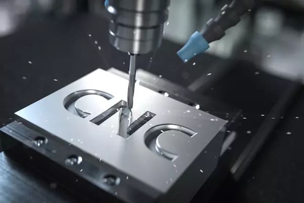
CNC rapid prototyping is the best choice when the prototype must behave like a precise part made from a known metal or engineering plastic. It is especially valuable for mating surfaces, threaded features, bearing locations, sealing faces, flat interfaces, and parts that will undergo mechanical or thermal tests.
Production grade material testing: Machining from the intended alloy or plastic provides more relevant stiffness, density, thermal behavior, and thread performance than a look alike material.
Fit critical assemblies: CNC equipment can control datums, bores, faces, and hole patterns according to a properly toleranced drawing and inspection plan.
Low quantity functional parts: A shop can make one or several parts without a dedicated mold. Setup, programming, tooling, and inspection still contribute to the quote.
Bridge production: The same basic subtractive process can support later low volume builds while demand or tooling decisions remain uncertain.
Surface and finish evaluation: Machined parts can receive processes such as anodizing, passivation, plating, polishing, or bead blasting when the selected supplier and material support them.
Three axis machining controls linear movement along X, Y, and Z. Five axis machining adds two rotary axes, which can reduce setups and reach more faces, but it does not make every geometry manufacturable. Internal sharp corners still reflect cutter shape, and deep narrow features still create access and tool deflection risks.
Rapid prototype machining is less suitable when the design depends on enclosed channels, lattice structures, or organic internal geometry that cannot be reached from the stock exterior. In those cases, additive manufacturing or a split assembly may be more practical.
Which Materials Work for CNC Rapid Prototypes?
Material selection for a CNC rapid prototype should follow the property being tested, not habit or the cheapest line item on a quote. If the final product uses plastic, an aluminum sample may verify geometry but misrepresent weight, flexibility, friction, insulation, and snap behavior.
| Material family | Common prototype choices | Useful test focus | Design or machining concern |
|---|---|---|---|
| Aluminum | 6061, 7075 | Lightweight structures, housings, fixtures, heat transfer | Alloy and temper affect strength, finish, and cost |
| Stainless steel | 304, 316 | Corrosion resistance, strength, medical or food equipment concepts | More cutting time and tool wear than many aluminum alloys |
| Carbon and alloy steel | 1018, 4140 | Shafts, brackets, wear or load testing | Heat treatment and corrosion protection may be relevant |
| Acetal | POM | Bushings, guides, low friction mechanisms | Dimensional response differs from metal |
| Nylon | PA | Wear parts, gears, lightweight mechanisms | Moisture absorption can affect dimensions and properties |
| Polycarbonate | PC | Impact resistant covers and functional housings | Stress, heat, and finishing require process awareness |
| PEEK | PEEK | High temperature or chemically demanding applications | Material cost makes stock planning important |
Specify the exact grade when properties matter. Trade names can be ambiguous, and phrases such as "aluminum" or "plastic" are not complete engineering requirements. Include any required temper, condition, color, certification, or approved equivalent in the request for quote.
What Drives Rapid Prototyping Cost and Lead Time?
Rapid prototyping cost and lead time are driven by material, machine time, setup count, tolerance, inspection, quantity, and secondary processing. Part size alone is a poor predictor because a small feature can demand a long toolpath or a separate setup.
Setup count: Each orientation may require new workholding, alignment, programming, and verification. Designing multiple critical features from a common accessible direction can simplify the plan.
Geometry: Deep pockets, narrow slots, thin walls, small internal corner radii, and long reach tools increase machining time and risk.
Tolerance and GD&T: Apply tight controls only where function requires them. ASME identifies Y14.5 as the authoritative guideline for stating and interpreting geometric dimensioning and tolerancing on drawings and digital product definitions.
Inspection: A basic dimensional report, a full first article inspection, material certificates, and calibrated CMM results are different deliverables with different costs.
Material availability: A common stocked grade can move faster than a special alloy, oversized billet, certified heat, or unusual plastic thickness.
Finishing: Anodizing, plating, heat treatment, polishing, and custom color matching add external process steps and queue time.
Quantity: More parts distribute programming and setup cost, but total cutting and inspection time still rises with quantity.
Ask suppliers to identify the main quote drivers instead of requesting a lower price with no design change. A useful response might suggest relaxing one nonfunctional tolerance, increasing an internal radius, changing stock size, or combining two features into one setup.
How Can You Design a CNC Prototype for Faster Machining?
A CNC prototype becomes faster and less expensive when the design gives cutting tools, fixtures, and inspection equipment clear access. The goal is not to simplify every feature, but to spend precision where the test needs it.
Label critical features: Mark the dimensions that control fit, sealing, alignment, motion, or safety. Do not apply a tight title block tolerance to every surface by default.
Use realistic internal radii: Internal corners are produced by round cutters. A larger radius often permits a stronger tool and a shorter toolpath.
Control depth to width ratios: Deep, narrow pockets require long tools that are less rigid. Open the geometry, reduce depth, or split the component when function allows.
Support thin walls: Thin sections can vibrate or deflect as material is removed. Add temporary stock, ribs, or a thicker prototype wall if the test does not require final thickness.
Design for workholding: Leave stable surfaces for clamping and consider how the part will be held after the first operation removes the original stock faces.
Separate cosmetic from functional finish: Define which surfaces are appearance critical and provide an acceptable sample or measurable requirement when color and texture matter.
Before release, review the design as both a part and a process. A feature that is easy to model may be difficult to cut, measure, or hold consistently.
What Should You Send to Rapid Prototyping Services?
A complete quote package gives rapid prototyping services enough information to price, manufacture, inspect, and track the correct revision. A 3D model alone rarely communicates every functional requirement.
Send the following items together:
A native or neutral 3D model: STEP is widely used for product data exchange. The ISO 10303 series defines principles for product information representation and exchange.
A controlled 2D drawing: Include datums, critical dimensions, tolerances, threads, surface finish, notes, and revision identification.
Material requirements: State grade, temper or condition, required certification, and whether equivalents are allowed.
Quantity by revision: Separate initial samples, test quantities, spares, and any expected follow on batch.
Finish requirements: Define finish type, color, masked areas, cosmetic surfaces, and acceptable variation.
Inspection requirements: Request only the records needed for the decision, such as critical dimension results, a full dimensional report, material certificates, or a first article report.
Use and test context: Explain whether the part is for fit, load, thermal, fluid, wear, appearance, or regulatory development testing.
Target date and delivery location: State when the parts are needed at the test site, not merely when they should leave the factory.
Use matching filenames and revision codes across the model, drawing, purchase order, and inspection report. When the model and drawing conflict, the supplier should know which document governs and should obtain written clarification before cutting material.
How Do You Evaluate a Rapid Prototyping Supplier?
A capable supplier should show that it can understand the test objective, control the specified process, verify critical requirements, and manage revision changes. A fast quote is useful, but it is not evidence that the finished part will answer the engineering question.
Ask these questions before placing the order:
Can you machine and document the exact material grade? Request a sample certificate when traceability is required.
Which features create the most cost or schedule risk? The answer reveals whether the quote included a real manufacturability review.
How will you inspect the critical characteristics? Confirm the method, sample size, report format, and whether measurement access exists.
Which operations are performed outside your facility? Finishing and heat treatment partners can affect lead time, traceability, and appearance consistency.
How are design revisions controlled? The supplier should prevent an obsolete model or drawing from reaching production.
Can the same process support the next quantity? This matters when the prototype may become a pilot build or bridge production part.
ISO states that ISO 9001:2015 defines requirements for establishing, maintaining, and continually improving a quality management system. Certification can support supplier evaluation, but it does not prove that a shop can hold every tolerance or execute every special process. Capability must still be matched to the specific part.
Common Rapid Prototyping Mistakes That Slow Development
Most rapid prototyping delays come from unclear decisions and uncontrolled information, not from the cutting or printing operation itself. These mistakes are preventable before the first quote.
Building before defining the test: The team receives a part but has no objective pass or fail criterion.
Choosing a process by speed alone: A visually accurate model may not reproduce the material, tolerance, or surface behavior required for functional testing.
Tolerancing every feature tightly: Unnecessary precision adds programming, machining, inspection, and rejection risk without improving the test.
Sending mismatched revisions: An updated model paired with an old drawing creates ambiguity and rework.
Ignoring measurement access: A requirement has little value if the feature cannot be inspected with the planned method.
Changing several variables at once: When geometry, material, and process all change between iterations, the team may not know which change caused the result.
Treat each build as a controlled experiment. Record the input revision, process, material, measured result, test outcome, and next decision so learning carries into the following iteration.
How PCBgogo Supports CNC Prototype Service for Precision Machining
A CNC prototype supplier should help engineers move quickly without losing control of material selection, dimensional requirements, or future production plans. PCBgogo's CNC Prototype Service for Precision Machining is positioned to support this process through quoting, precision manufacturing, and production scalability.
Fast quoting and flexible material selection: PCBgogo provides a streamlined quotation process and access to a range of engineering materials for different functional requirements. Early review of the CAD files, drawings, material grade, quantity, and finish requirements helps identify potential manufacturing issues before machining begins.
Precision equipment for demanding components: PCBgogo uses precision machining equipment to produce CNC parts for applications where fit, alignment, surface condition, and dimensional accuracy matter. Critical dimensions should still be clearly identified on the drawing so machining and inspection resources can focus on the features that control product performance.
Support from prototype to production: A validated CNC prototype may need to progress into pilot builds, bridge production, or higher volume manufacturing. PCBgogo supports that transition, helping customers maintain consistent design information and manufacturing requirements as quantities increase.
For teams that need functional parts rather than visual models alone, working with one supplier from the first prototype through production can reduce supplier handoffs and preserve manufacturing knowledge between revisions. Before requesting a quote, prepare the 3D model, controlled drawing, material specification, quantity, finish, inspection requirements, and target delivery date.
Frequently Asked Questions About Rapid Prototyping
Rapid prototyping questions usually focus on speed, process choice, cost, and the information a supplier needs. The answers below provide practical starting points, but the CAD model and test plan determine the final approach.
How fast can a rapid prototype be made?
A simple prototype can sometimes be manufactured quickly, but delivery depends on material availability, geometry, machine capacity, inspection, finishing, and shipping. Ask for a schedule that separates design review, manufacturing, secondary processing, inspection, and transit.
Is CNC machining considered rapid prototyping?
Yes. CNC machining is a rapid prototyping method when it is used to create test parts quickly from digital design data, especially when production grade material and precise features are required.
Is CNC better than 3D printing for prototypes?
CNC is usually better for precise functional parts in known stock materials, while 3D printing is usually better for complex geometry and early form checks. The better choice is the process that reproduces the property being tested.
What files are needed for CNC rapid prototyping?
Send a 3D CAD file plus a controlled 2D drawing when tolerances, threads, finishes, or inspection requirements matter. Include the material grade, quantity, revision, test purpose, and delivery location.
How much does a rapid prototype cost?
There is no reliable flat price because setup count, machine time, material, tolerance, inspection, finishing, and quantity vary by design. Request itemized options when you want to compare the cost impact of a material, tolerance, finish, or quantity change.
Can a rapid prototype use the final production material?
Yes, CNC machining and some other processes can use the intended production material. Confirm the exact grade and condition because matching a material name does not automatically reproduce a molded, cast, forged, printed, or heat treated production microstructure.
Conclusion
Successful rapid prototyping begins with a test question, then matches process, material, tolerances, and inspection to the evidence needed. Define what the part must prove, send a revision controlled quote package, and choose a supplier that can explain both manufacturability and measurement before production starts.





