
What Is SMT? A Complete Guide to Surface Mount Technology
KEY DEFINITION SMT (Surface Mount Technology) is a PCB assembly method where components are soldered directly onto the surface of a printed circuit board, rather than inserted through drilled holes. An SMT component, also called an SMD, sits on solder paste that is melted in a reflow oven. SMT enables smaller boards, higher component density, and faster automated assembly compared to through-hole methods.
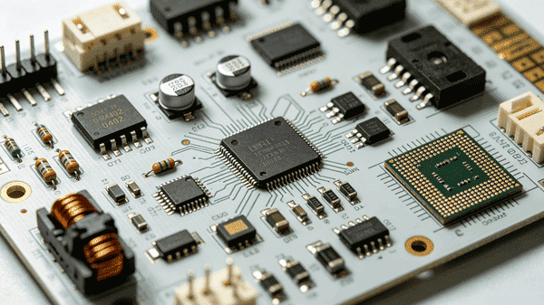
Pull apart an old radio and a modern smartphone and the difference is obvious. One is full of wires threaded through holes and soldered by hand. The other is a dense grid of components small enough to sit flush on the board surface, placed by machines. That shift is SMT.
This guide covers what SMT is, the components it uses, how the assembly process works, and where it differs from through-hole assembly.
What Is Surface Mount Technology?
Surface Mount Technology is a PCB assembly process where components are mounted and soldered directly onto pads on the board's surface instead of having leads inserted through drilled holes. It replaced through-hole assembly as the dominant manufacturing method starting in the 1980s and now accounts for the vast majority of PCB assembly in consumer, industrial, and automotive electronics.
The core mechanism is straightforward: solder paste holds a component in place on a pad, then heat melts that paste to form a permanent electrical and mechanical bond. Because there is no need to drill holes or bend leads, boards can be populated with far smaller components on tighter spacing. A typical SMT resistor in an 0402 package measures just 1.0mm by 0.5mm, compared to a through-hole resistor that can run 6mm or longer.
SMT vs SMD: What Is the Difference?
SMT is the assembly process, SMD is the component built for that process. The terms are often used interchangeably, but they describe two different things: SMT refers to the manufacturing method, including solder paste application, machine placement, and reflow soldering. SMD refers to the physical component, such as a chip resistor or a QFN package, built with flat contacts instead of wire leads.
| Term | Stands For | What It Describes |
|---|---|---|
| SMT | Surface Mount Technology | The assembly process used to mount components on a PCB |
| SMD | Surface Mount Device | The component itself, designed for surface mounting |
| PCB | Printed Circuit Board | The board that SMDs are mounted onto |
This distinction matters when reading datasheets or ordering parts: a supplier lists a part as an "SMD" while describing the manufacturing line as "SMT assembly."
What Is an SMT Component?
An SMT component is any electronic part with flat metal contacts instead of through-hole leads, built to be soldered directly onto a PCB surface. These fall into a few main categories:
Chip resistors and capacitors: Sized in standard packages like 0402 (1.0mm x 0.5mm) or 0603 (1.6mm x 0.8mm), these are the most common SMT components by volume.
Integrated circuits (ICs): Packaged as QFN (Quad Flat No-lead), QFP (Quad Flat Package), or BGA (Ball Grid Array), with pin counts ranging from single digits to several hundred.
Diodes and transistors: Typically housed in SOT (Small Outline Transistor) packages for a minimal footprint.
Connectors and inductors: Designed with surface-mount tabs or pads instead of the pins used in through-hole connectors.
Because these parts lack long leads, they require precise placement and controlled soldering, which is why SMT assembly relies on automated equipment beyond the prototype stage.
The SMT PCB Assembly Process, Step by Step
SMT PCB assembly follows a consistent sequence regardless of the product. Each stage exists to control a specific failure mode, from misaligned paste to weak solder joints.
1. Solder paste printing. A stainless steel stencil is aligned over the PCB, and solder paste, a mixture of tiny solder particles and flux, is spread across it so paste deposits only on the pads. Too much paste causes bridging between pins; too little causes weak or open joints.
2. Solder paste inspection (SPI). Many production lines use 3D optical systems to check paste height, area, and volume immediately after printing, catching deposition errors before components are placed.
3. Pick-and-place assembly. Automated machines position each SMD onto its paste deposit using vacuum nozzles and camera-guided alignment, placing components with accuracy down to roughly 0.01mm at rates of thousands of parts per hour.
4. Reflow soldering. The populated board passes through a reflow oven with a staged temperature profile, typically peaking around 245°C for lead-free solder, which melts the paste and forms the final connection as the board cools.
5. Inspection and testing. Automated Optical Inspection (AOI) scans for missing parts, misalignment, or bridging, while X-ray inspection checks hidden joints under packages like BGAs. Electrical testing then confirms the assembled board performs as designed.
Knowing what each stage of the line is checking for makes it easier to evaluate a fabricator that documents its process at every step, rather than treating it as a black box.
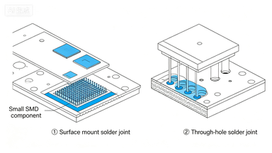
SMT vs Through-Hole Technology
Through-hole technology mounts components by inserting leads through drilled holes and soldering them on the opposite side, while SMT mounts components directly onto the surface pads. Both methods are still used today, often on the same board.
| Factor | SMT | Through-Hole |
|---|---|---|
| Component size | Smaller, higher density | Larger, more spacing needed |
| Assembly speed | Fast, fully automatable | Slower, often manual for complex parts |
| Mechanical strength | Lower per joint | Higher, better for connectors and heavy parts |
| Typical use | Consumer electronics, high-density boards | Power connectors, components under mechanical stress |
| Rework | More difficult on fine-pitch parts | Easier to desolder and replace |
Many modern boards use both. This mixed configuration, sometimes called Type II assembly, places SMT components for density and through-hole components for parts that need a mechanically robust connection, such as edge connectors.
Common SMT Soldering Defects and How to Prevent Them
Even a well-controlled SMT line produces defects when paste volume, placement accuracy, or reflow temperature drift out of spec. Knowing the common failure modes makes them easier to catch during inspection.
| Defect | Cause | Prevention |
|---|---|---|
| Tombstoning | Uneven heating lifts one end of a small component | Balance pad thermal mass, control reflow ramp rate |
| Solder bridging | Excess paste or fine-pitch spacing | Reduce paste volume, verify stencil aperture design |
| Cold solder joints | Reflow temperature too low or ramp too fast | Follow a validated reflow profile for the paste alloy used |
| Insufficient wetting | Contaminated pads or expired paste | Use fresh paste, confirm pad finish is within spec |
According to IPC-A-610, the industry standard for electronic assembly acceptability, solder joints are classified by defect severity across three product classes, giving fabricators a shared benchmark for an acceptable joint versus one requiring rework.
Catching these issues consistently comes down to process discipline. A fabricator that runs SPI and AOI on every board, rather than spot-checking, cuts down on defects that would otherwise surface only after the board reaches a customer. PCBgogo runs SMT assembly lines with SPI, AOI, and X-ray inspection built into the standard process, so boards are checked at each stage rather than only at final QC.
Why SMT Matters for Modern Electronics
SMT is the reason modern electronics can be small, fast to produce, and dense with functionality at the same time. Without it, the component density inside a smartphone or wearable device would not fit on a board of that size.
The performance benefit compounds the size benefit. Shorter interconnects between SMT components reduce parasitic inductance and capacitance, which matters directly for high-speed and RF designs where signal integrity depends on minimizing trace length.
FAQs
What does SMT stand for?
SMT stands for Surface Mount Technology, the PCB assembly method where components are soldered directly onto the board's surface instead of through drilled holes.
Is SMT the same as SMD?
No. SMT is the assembly process, while SMD (Surface Mount Device) refers to the individual component designed to be mounted using that process.
What is the difference between SMT and THT?
SMT mounts components directly onto surface pads, while THT (through-hole technology) inserts component leads through drilled holes and solders them on the opposite side. SMT allows for smaller, denser boards, while THT offers stronger mechanical connections for parts under physical stress.
What temperature is used in SMT reflow soldering?
Lead-free reflow soldering typically peaks around 245°C, following a staged profile that preheats, soaks, and then briefly reaches peak temperature before cooling to avoid thermal damage to components.
Can SMT and through-hole components be used on the same board?
Yes. This is called mixed assembly, and it is common on boards that need SMT's density for most components alongside through-hole connectors or parts that require a stronger mechanical joint.
Conclusion
SMT replaced through-hole assembly as the standard method for building modern circuit boards because it enables smaller components, higher density, and faster automated production. Understanding the process, from solder paste printing through reflow and inspection, makes it easier to specify a board correctly and spot a quality assembly partner.
If you're preparing a design for SMT assembly, PCBgogo supports both prototype and production runs with standard inspection built into every build.


