




 日本語
日本語
 한국어
한국어

PCB Design & Layout Practical Guide for Reliable Boards
KEY DEFINITION PCB design & layout converts a verified schematic into a manufacturable board by defining geometry, footprints, component placement, stackup, copper routing, return paths and thermal paths, while applying production rules. Best-in-class layout workflows establish fabrication constraints first, place components following signal flow, route critical nets prior to ordinary signals, and validate electrical, mechanical and manufacturing details before release.
A PCB can be electrically correct on screen and still fail in the finished product. Poor connector placement can prevent assembly, broken return paths can increase noise, undersized copper can overheat, and unnecessarily complex features can raise manufacturing costs. These problems occur when schematic design, mechanical constraints, layout decisions, and fabrication requirements are handled separately.
Effective PCB design & layout brings these factors together from the beginning. This guide follows the complete engineering workflow, covering schematic and footprint verification, board shape and stackup planning, component placement, trace routing, board type selection, and final manufacturability review.
What PCB Layout Design Controls
PCB layout design is the physical implementation of a circuit: it assigns every component to a real footprint, places those footprints inside a defined board outline, and connects their pads with copper that can be fabricated and assembled. It also defines the layer stack, reference planes, holes, keepouts, solder mask, silkscreen, test access, and manufacturing notes.
The layout must satisfy circuit behavior, mechanical fit, fabrication capability, and assembly process at the same time. A fast signal needs a sound return path, a power device needs a thermal path, and a connector may have only one viable location. Resolve these constraints before routing becomes crowded.
PCB Design and Layout Workflow from Requirements to Release
A dependable PCB design & layout process converts product requirements into explicit constraints before copper is drawn. Use the following sequence, and allow controlled iteration when routing exposes a placement or stackup problem.
Define the product. Record supply rails, interfaces, maximum currents, operating environment, enclosure limits, connector positions, test needs, and target board type.
Verify the schematic. Run ERC, confirm pin maps and power pins, and mark critical nets such as clocks, differential pairs, switch nodes, and analog inputs.
Validate footprints. Compare pads, holes, body size, polarity, and pin 1 against the component drawing.
Set geometry and stackup. Import the board outline, place holes and keepouts, and agree on layers, finished thickness, and impedance with the fabricator.
Enter design rules. Use manufacturing limits as hard floors and define net classes for routine signals, power, high voltage, and controlled impedance.
Place and route. Lock mechanical parts, place by signal flow, minimize critical loops, route priority nets first, and preserve return paths.
Release a controlled package. Run ERC and DRC, check the 3D fit, inspect outputs, and issue fabrication, drill, BOM, and assembly data under one revision.

Start with a Schematic That Can Drive the Layout
A layout ready schematic expresses design intent, not only connectivity. Keep functional blocks readable, use consistent net names, and show connectors, power pins, decoupling, programming access, and test points explicitly. Check copied symbols and hidden power pins against the source data.
Add constraints while the circuit is readable. Classify high current rails, clocks, differential pairs, analog nodes, switch nodes, and nets needing length or impedance control. Mark intentional no connects, then run ERC and cross check the netlist before placement.
What a PCB Footprint Must Define
A PCB footprint is the complete physical interface between a component and the board, including copper lands, holes, solder mask openings, paste apertures, courtyard, assembly outline, reference text, and orientation marks. A footprint is correct only when its numbering matches the symbol and its geometry matches the purchased package.
Use the manufacturer's package drawing as the primary source, then apply IPC 7352 land pattern guidance and the assembly process to set land protrusion and spacing. Check the exact package variant, verify mating direction and body height in 3D, and define QFN paste segmentation and thermal via treatment with the assembler rather than copying a generic footprint.
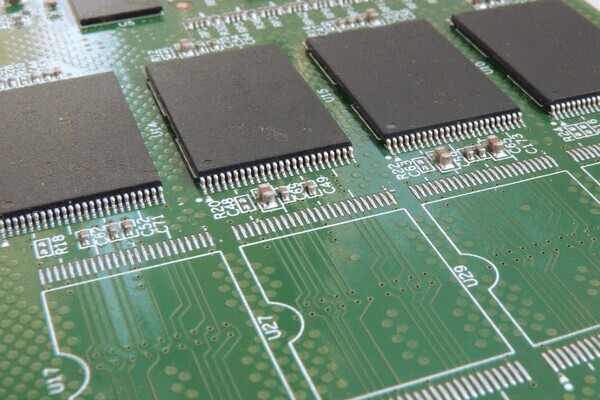
Board Shape and Size Must Follow the Product
PCB shape and size should be derived from the enclosure, mounting method, connector access, user controls, and manufacturing panel rather than chosen after routing. Import a controlled mechanical outline and establish a common origin so the ECAD and mechanical CAD models stay aligned.
Place holes, edge connectors, controls, antennas, displays, and height restricted zones before ordinary components. Define keepouts around screws, clips, cutouts, edges, and tooling features with the fabricator and mechanical designer. Check the assembled 3D model for lid clearance, cable bend, tool access, and connector engagement.
Component Placement Rules That Improve PCB Layout
Effective placement shortens critical current loops and makes routing, cooling, inspection, and rework predictable.
Mechanical anchors. Place fixed connectors, holes, controls, and edge facing parts first. Lock them after mechanical review.
Functional blocks. Keep power, processing, memory, analog, and communications blocks coherent and follow schematic signal flow.
Decoupling loops. Place each bypass capacitor beside its power pin with a short connection to the reference plane.
Noisy and sensitive regions. Separate switch nodes, inductors, crystals, antennas, and high impedance analog inputs while controlling their return paths.
Thermal paths. Give hot parts useful copper and airflow, protect temperature sensitive parts, and reserve room for thermal vias or heat sinks.
Assembly and test access. Keep polarity marks visible and leave probe and rework access around required parts.

Trace Routing Rules for Signal Power and Return Current
PCB routing connects pads while controlling current flow, voltage drop, electromagnetic interference, heat, and manufacturability. Route critical nets first, including clocks, memory buses, differential pairs, RF signals, high current paths, switching loops, and sensitive analog signals. Complete ordinary control and low speed signals afterward.
Reference continuity. Route high speed signals over an uninterrupted reference plane. Avoid crossing plane splits, voids, or large cutouts because they force return current to take a longer path and increase loop area, noise, and electromagnetic emissions.
Power integrity. Determine trace and copper area from current, copper thickness, permitted temperature rise, and acceptable voltage drop. Check narrow sections, connector pins, vias, and layer transitions because the smallest cross section often limits the complete power path.
Controlled impedance. Finalize the PCB stackup before calculating trace geometry. Impedance depends on trace width, copper thickness, dielectric thickness, material properties, reference planes, solder mask, and differential pair spacing.
Differential pairs. Route both conductors on the same layer with consistent width, spacing, and reference. Keep the pair symmetrical, reduce unnecessary vias, and match length according to the interface specification rather than applying the same tolerance to every differential signal.
Vias and layer changes. Minimize layer transitions on critical signals. When a signal changes layers and also changes reference planes, place a nearby return via so the return current can follow the signal transition without creating a large loop.
Decoupling connections. Place each decoupling capacitor close to its target power pin. Connect the capacitor to the power and ground system through short, wide paths with nearby vias. The goal is to minimize the complete current loop, not simply the visible trace length.
Corners and flex regions. Use clean 45 degree bends or arcs where practical. In flexible sections, route traces perpendicular to the bend line, use smooth transitions, and keep vias, pads, and abrupt width changes outside the bend zone.
How Rigid Flexible and Rigid Flex Boards Change the Design
Rigid, flexible, and rigid-flex boards implement a netlist with different mechanical structures, so they need different placement, copper, and documentation rules.
| Board type | Best fit | Layout focus | Routing and mechanical rule |
|---|---|---|---|
| Rigid PCB | Stable component platform | Stackup, planes, thermal paths, enclosure fit | Use normal rigid board clearances and support heavy or stressed parts |
| Flexible PCB | Light interconnect that bends or folds | Bend region, stiffeners, coverlay, copper grain | Route conductors across the bend, use smooth transitions, and keep holes out of the bend zone |
| Rigid-flex PCB | Rigid component areas joined without cable connectors | Multiple regional stackups and rigid to flex transitions | Document every region, layer transition, bend direction, and installed shape |
For flex circuits, first determine whether the board will bend only during installation or move repeatedly during operation. Static and dynamic applications require different materials, stackups, and bend geometry. A common starting point is a minimum bend radius of five times the circuit thickness for single layer flex, ten times for double sided flex, and fifteen times for multilayer flex. Dynamic applications may require a bend radius of 20 to 40 times the circuit thickness, fewer flex layers, rolled annealed copper, and additional strain relief. These ratios are preliminary design values. The PCB manufacturer should confirm the final stackup, bend direction, bend radius, copper type, and expected flex cycle count before production.
Single Layer and Multilayer Layouts Need Different Strategies
A single layer board must solve routing on one copper side, while a multilayer board uses internal copper and reference planes for density, return paths, and power distribution. Choose layer count from electrical and mechanical needs.
| Design issue | Single layer | Multilayer |
|---|---|---|
| Routing | Plan placement around one usable copper layer; jumpers may be needed | Assign layers by signal class and route direction |
| Return path | Often wider and less continuous; loop area needs careful control | Use adjacent solid planes for predictable high frequency return |
| Power | Use wide traces or pours and check voltage drop | Use planes or broad shapes with planned via transitions |
| EMI and density | Best for simple low density circuits | Better control for dense, high speed, or mixed signal designs when stackup is planned |
| Release review | Check jumper count, solder side access, and copper balance | Check plane continuity, layer transitions, stack symmetry, and impedance notes |
PCB design requirements vary by board construction. IPC 2221 covers general printed board design principles, IPC 2222 addresses rigid organic PCBs, and IPC 2223 applies to flexible and rigid-flex circuits. Select the standard that matches the board type, then combine its guidance with the PCB manufacturer’s current material, stackup, trace, spacing, drilling, and process capabilities.
How to Improve a PCB Layout Before Release
A PCB layout improves fastest when every review tests a different failure mode instead of repeating a general visual inspection. Use a short, disciplined sequence.
Manufacturing review. Check trace, spacing, drill, annular ring, edge, solder mask, stackup, and panel rules against the fabricator's data.
Electrical review. Follow every critical signal from source to load and inspect its reference, termination, layer changes, and nearby aggressors.
Power and thermal review. Check current paths, neckdowns, via capacity, copper balance, hot spots, and airflow.
Mechanical and assembly review. Inspect 3D fit, orientation, spacing, tool access, fiducials, test points, and panel handling.
Independent final check. Open Gerbers and drill files in a separate viewer and confirm their revision matches the BOM and assembly data.
How PCBgogo Turns the Layout into Manufacturable Hardware
Passing DRC does not automatically make a PCB layout ready for production. The design still has to be translated into a physical stackup, drill structure, copper geometry, solder mask, surface finish, panel configuration, and inspection plan that the manufacturing process can reproduce consistently. This is where close coordination with the PCB manufacturer becomes essential.
PCBgogo supports the transition from completed layout to finished hardware through a connected engineering and production workflow.
Manufacturing data review. PCBgogo reviews the Gerber files, drill files, board outline, stackup, fabrication notes, and impedance requirements as one complete package. This confirms that the production data matches the designer’s intended layer order, board thickness, copper weight, hole structure, surface finish, and mechanical dimensions.
Controlled PCB fabrication. Once the data is confirmed, PCBgogo controls each manufacturing stage according to the approved design requirements. Material selection, imaging, etching, copper deposition, hole plating, lamination, solder mask application, surface finishing, and profile routing are carefully managed because these processes can affect copper geometry, electrical performance, heat distribution, mechanical strength, and long term reliability. This process control helps minimize differences between the finished PCB and the released design data.
Inspection and electrical testing. After fabrication, inspection and electrical testing verify that the finished PCB meets the approved requirements. These checks can identify pattern defects, registration issues, opens, shorts, and other production problems. Controlled impedance testing can also be performed when it is specified in the design package.
PCB assembly. If assembly is required, PCBgogo can continue with stencil preparation, component placement, reflow soldering, and through hole assembly using the same approved PCB revision. Keeping fabrication and assembly within one coordinated workflow reduces file mismatches and makes it easier to resolve footprint, component, and soldering issues.
Keeping these stages connected helps preserve design intent from the PCB layout through fabrication and assembly. Instead of discovering footprint, stackup, impedance, or assembly problems after boards have been produced, designers can resolve them while changes are still practical. By submitting a complete and controlled manufacturing package to PCBgogo, engineers can move from a verified PCB layout to a buildable prototype and then scale the same design toward production with fewer avoidable revisions.
PCBgogo - Reliable, High-Quality PCB Manufacturing
Save time and money with an all-in-one solution for PCB fabrication, assembly, and parts. Reduce vendor coordination, avoid split shipments, and get consistent, reliable quality.
Get Free Quote >
Turn a Verified Layout into a Reliable PCB
A successful PCB layout must do more than connect every net. It must fit the product, preserve signal and power integrity, manage heat, support assembly, and remain within practical manufacturing limits.
Build these requirements into the design from the beginning, then verify the schematic, footprints, stackup, placement, routing, mechanical dimensions, and final production files as one connected system. Before release, PCBgogo can review the manufacturing data, identify potential producibility issues, and help convert the verified layout into a PCB that closely follows the intended electrical and mechanical design.
Frequently Asked Questions
What Is the Difference Between a PCB Schematic and PCB Layout
The PCB schematic defines electrical connectivity and design intent, while the PCB layout defines the physical board, footprints, placement, copper, holes, and production layers. A correct schematic is necessary, but physical performance depends on how the layout controls current paths, coupling, heat, and manufacturing limits.
How Wide Should PCB Traces Be
Trace width should be calculated from current, copper thickness, allowed temperature rise, voltage drop, impedance target, and the fabricator's process. Use separate net classes for ordinary signals, power, high voltage, and controlled impedance rather than one width for the whole board.
Should a Simple Design Use Two Layers or Four Layers
Two layers can suit low density and modest speed designs when routing and return paths remain clean. Four layers are often the better engineering choice when the design needs continuous reference planes, lower loop inductance, easier power distribution, or less routing congestion.
When Should a Design Use Rigid Flex Instead of Connectors
Rigid-flex is useful when space, weight, repeated assembly, vibration, or connector reliability justifies integrating the interconnect into the board. Compare the full installed assembly, including cables, connectors, labor, and failure points, then involve the fabricator before fixing the flex stack and bend geometry





