Why Use Metal Core PCB Instead of Standard PCB in LED Based Products?
With the development of electronic technology, LED based products more and more popular, consequently, and even is metal core PCB. Now metal core PCB has applied in the automobile and lighting sectors, there is a result shown that LED based light can be more efficient and nearly 5 times cheaper than normal incandescent units. However, LEDs convert a small part of the input electrical power as heat as with other electrical devices. It’s difficult to make sure stable and reliable LED operation, as well as make full use of the complete performance and efficiency of the LEDs if it does not dissipate the thermal loss. So designers have solved the problem of dissipating heat from LEDs with metal core PCBs.
What are Metal core PCBs (MCPCBs)?
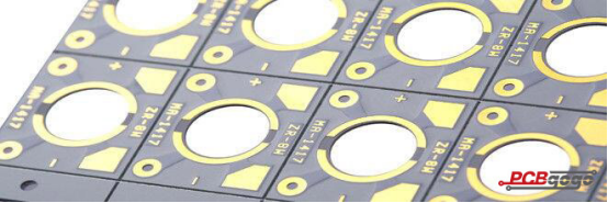
Metal Core PCBs or MCPCBs are the types of PCBs that contain a base metal material as opposed to the traditional FR4. The core is usually designed to redirect heat away from the components. The metal core is composed of a metal plate of a particular thickness which dissipates heat.

Metal core PCB materials and thickness
The metal core of the thermal PCB can be aluminum (aluminum core PCB), copper (copper core PCB or a heavy copper PCB) or a mixture of special alloys. The most common is an aluminum core PCB.
The thickness of metal cores in PCB base plates is typically 30 mil - 125 mil, but thicker and thinner plates are possible. MCPCB copper foil thickness can be 1 - 10 oz.
Metal core PCB advantages
On one hand, metal core PCB is mainly in improving the reliability of devices that run at slightly higher temperatures. Not only does it allow for components to be mounted, but also draws heat from hot-running components to the other side of the board where it is dissipated, which will improve performance and life. As well as metal core PCB has great effect on solving the problem of overheating caused by large number of LEDs in devices.
On the other hand, metal core PCB can make full use of its ability to integrate a dielectric polymer layer with a high thermal conductivity for a lower thermal resistance.
What is the difference between metal core PCB and standard epoxy glass PCB?
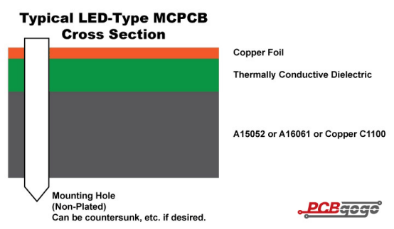
One important difference to understand between metal core PCB and standard PCB is how the materials work together to create the necessary result. In metal core PCB, there is a single layer of copper with is bonded to a layer of conductive dielectric material, which is further bonded to a thick metal layer (typically Aluminum 5052, Aluminum 6061, or Copper C1100). The dielectric used is approximately 6-7 times as thermally conductive as FR4. The dielectric is to be kept as thin as possible. This reduces the distance from the heat source to the metal plate which is more conductive than the dielectric.
As you know, the metal plate on the bottom side is the thickest element in the structure. It is available in several different thicknesses, however, there are three most common thickness, such as 1.0mm, 1.5mm, and 3.2mm as they are the easiest to purchase. The metal also gives the PCB rigidity and does not require any surface finish or solder mask.

Metal core PCB surface mounted components
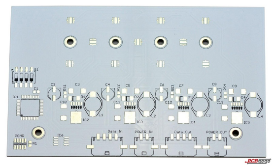
A key factor to incorporate into your metal core PCB design is to not use any plated through holes and instead use only surface-mounted components. This is because a plated through hole can cause a short circuit as the bottom layer is metal. In normal LED PCBs the layers usually have plated vias which allow components to transmit heat. During soldering some solder can enter these vias if not filled and can cause errors. On the other hand in metal core PCB operate differently.
Vias are not required as the metal layer is efficiently thermally conductive. Instead they require drilling of a few large mounting holes. This also helps the manufacturing process to move faster. After the drill cycle, the single layered MCPCB goes straight to circuit imaging rather than passing through the electroless copper deposition in PTH processing. After this the process is similar to the standard FR4 PCB.
Metal core PCB manufacturer considerations
There are some processing tips for MCPCB manufacturing, however if only you understand the way the materials work and you keep your design to a single-layer SMT-only type, then designing your board should be much the same as any other single-layer PCB. If you find that you cannot route your design to a single layer, note that other metal core PCB configurations are possible, despite they fall outside of the scope of this piece. These include as follows:
2-layer, PTH boards with aluminum on the inside, which requires a costly pre-drill, fill with insulation, as well as re-drill step to form plated through holes that won’t short.
2-or-more layer PCBs built on standard PCB processes, however using thermal dielectric material instead of FR4, and a metal plate laminated to the bottom for thermal transfer.
When cooling of multiple LEDs is a design priority, metal core PCB can be an excellent solution. They are becoming more and more common in a variety of lighting applications – for home, workplace, and vehicle. Despite metal core PCBs are subject to certain design restrictions, the manufacturing process is the same as most other PCBs, and it is more simple in some ways.
FR-4 PCB Vs. Metal core PCB comparison
Plated through holes: in general, plated through holes are used in FR-4 PCB. It can be through hole components if required. In metal core PCB, plated through holes are not available for 1-layer PCB. All components are surface-mounted.
Conductivity: FR-4 PCB has low thermal conductivity, in general about 0.3W, however, MCPCB has higher thermal conductivity between 1.0W and 4.0W, most commonly about 2.0W.
Thickness: FR-4 PCB has a wide range of thickness, also uses many material combinations and layers. Metal core PCB have limited thickness variation.
Thermal relief: as usual, Thermal relief in FR4 PCB involves vias for heat transfer. And it has a longer drilling processing cycle. Metal core PCBs don’t require via as their own thermal dissipation. Consequently, they do not require via drilling, deposition and plating processes.
Solder mask: FR-4 PCB solder mask is dark colors such as green, red, black and so on, which usually applied on top and bottom. For LED boards, metal core PCB solder mask are almost exclusively white and they are only applied to the top.
Machining process: FR-4 PCB uses standard processing such as drilling, routing, v-scoring, countersink, counterbore and so on. whereas in metal core PCBs, there is a distinctive difference in the v-scoring process i.e. diamond coated saw blades are used for the added strain from cutting into metal.

Applications of metal core PCBs
Apart from using in LED lights, you can find metal core PCBs being used in several other applications. For example, the size constraints and watt-density requirements of DC-DC converters force engineers to use metal core PCBs, because they can be compatible with mechanical fasteners with a variety of thermal performances, and are highly reliable. It can use the metal core PCBs in various form factors and manufacturers can fabricate substrate metals in a wide variety with different thicknesses and copper foil weights.
Now metal core PCBs are widely used in automotive, audio, motor control and power conversion, which have some advantages such as superior attachment capabilities, excellent thermal performance, as well as surface mount assembly. In general, manufacturers will remove the dielectric and create the metal core with 3-D features so that make the metal core to be a versatile substrate.
The material structure of metal core PCBs can be used in solid-state relays of mounting configurations in some control applications, which is impossible for ceramic substrates.
Metal core PCBs provide thermally efficient and mechanically robust construction that a solid-state relay construction demands. Manufacturers are discovering new types of metal core PCB material, especially dielectrics, to meet the demands of high thermal performance that can even out-perform existing ceramic-based designs.
