
 日本語
日本語
 한국어
한국어

Welding Defects Explained: Causes, Prevention and CNC Quality Control
QUICK ANSWER Welding defects are unacceptable flaws that keep a joint or fabricated part from meeting its drawing, code, or service requirements. Surface defects are often visible, while internal defects usually require nondestructive testing. Effective control starts before the arc with correct joint geometry, clean material, stable parameters, restrained fit-up, and a documented inspection plan.
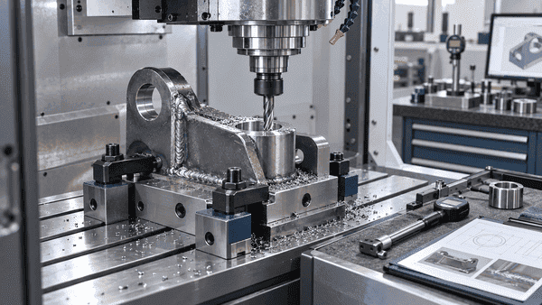
Welded components often return to a machine tool for datum restoration, hole finishing, or final tolerances. Heat distortion may shift a bore, spatter can damage a finished surface, and a poor repair can remove stock needed for final sizing. When a project combines welding with custom CNC machining, plan the welding sequence and machining allowances as one process.
What Are Welding Defects
A welding discontinuity is any interruption in the expected structure or profile of a weld. It becomes a defect when its type, size, location, or frequency exceeds the acceptance criteria on the drawing, contract, or applicable welding standard. This distinction matters: a minor profile variation may be permitted in one noncritical bracket but rejected in a pressure-retaining or fatigue-loaded assembly.
Welding defects can reduce load capacity, fatigue life, corrosion resistance, dimensional accuracy, or appearance. Define the joint category, inspection scope, and acceptance limits before production. Without them, “good weld” is only an opinion.
External and Internal Welding Defects
External defects occur at or break the weld surface and are often visible. Internal defects lie inside the weld metal or along the fusion boundary. Location alone does not determine severity: a small surface crack may be more dangerous than rounded internal porosity. Shape, orientation, material, loading, and service environment also matter.
| Defect group | Typical indications | Useful first inspection |
|---|---|---|
| Surface profile | Undercut, overlap, excess reinforcement, underfill | Visual testing and gauges |
| Surface breaking | Cracks, open porosity, mechanical damage | Visual, penetrant, or magnetic particle testing |
| Volumetric | Internal porosity and slag inclusions | Radiographic or ultrasonic testing |
| Planar internal | Incomplete fusion, incomplete penetration, internal cracks | Ultrasonic testing or qualified radiography |
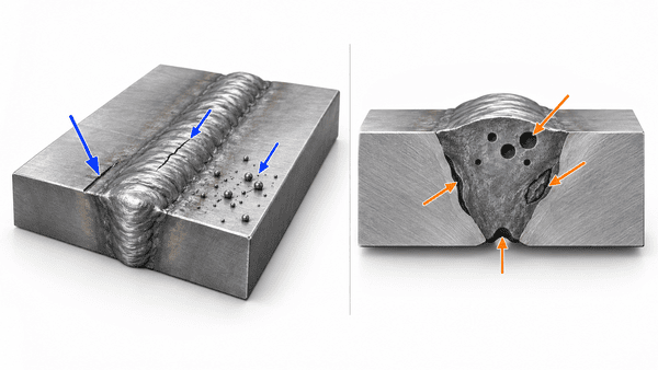
External Welding Defects
Cracks
Cracks are sharp separations in the weld or heat-affected zone. Hydrogen, rapid cooling, high restraint, unsuitable filler, or an unfilled crater can cause them. Use dry consumables, clean joints, correct preheat and interpass control, compatible filler, balanced sequencing, and proper crater fill.
Porosity
Porosity consists of gas pockets that may open at the surface or remain hidden. Moisture, oil, rust, paint, excessive arc length, drafts, or poor shielding gas flow are frequent causes. Clean and dry the joint, protect the gas envelope, check hoses and flow rate, maintain a stable arc, and use suitable parameters.
Undercut
Undercut is a groove melted beside the weld toe and left unfilled. Excess current, fast travel, long arc length, or poor electrode angle can cause it. Reduce heat input as needed, slow the travel enough to fill the toe, keep the correct angle, and use multiple passes where one large pass is difficult to control.
Overlap
Overlap occurs when weld metal rolls onto the base metal without fusing to it. Low travel speed, excessive deposition, low heat input, or a poor torch angle are typical causes. Match current to wire size, maintain controlled travel, direct the arc into the joint faces, and avoid depositing more metal than the joint can accept.
Burn Through
Burn-through leaves a hole or collapsed root, especially in thin material or an oversized root gap. Excess current, slow travel, and poor backing make it more likely. Use a tighter fit-up, lower heat input, faster controlled travel, pulse settings where suitable, tack spacing that holds the gap, or a compatible backing bar.
Spatter
Spatter is scattered molten metal attached around the weld. It often points to excessive current or voltage, unstable wire feed, incorrect polarity, contamination, or poor gas selection. Tune the transfer mode, verify polarity and feed, clean the surface, maintain the contact tip, and shield nearby finished faces. If appearance matters, define the required CNC surface finish before welding so masking and cleanup do not alter critical dimensions.
Underfill
Underfill means the weld face or root remains below the adjacent base surface. Insufficient filler, fast travel, or poor pass placement can cause it. Correct deposition and travel speed, verify groove volume, place each bead deliberately, and inspect the final profile.
Excess Reinforcement
Excess reinforcement is an overly high or convex weld face. Too much filler, slow travel, low voltage, or poor joint access can create stress concentration and obstruct later machining. Use the specified weld size, balance deposition with travel speed, and confirm clearance for cutters, fixtures, and mating components.
Mechanical Damage
Arc strikes, grinder gouges, tool marks, and dents can introduce hard zones or stress risers. Use protected surfaces, controlled handling and grinding, and clear repair limits. Before grinding, check the remaining wall thickness and machining allowance.
Distortion
Uneven heating and shrinkage can bow plates, rotate flanges, or shift machined features. Use balanced sequences, smaller passes, adequate tacks, fixtures, presetting, and the lowest qualified heat input. Leave machining stock only where the plan can reference stable datums afterward.
Misalignment
Misalignment is an offset between joint members or features that should share a position or axis. Poor fit-up, inconsistent tack welds, weak fixturing, or distortion may cause it. Machine accurate locating features, inspect the assembly before welding, clamp from functional datums, and recheck alignment after tacking. Thoughtful CNC chamfer design can also improve weld access and repeatable edge preparation when specified for the joint.
Internal Welding Defects
Slag Inclusion
Slag inclusion is nonmetallic residue trapped between passes or at a joint boundary. It develops when slag is not removed, the groove is too narrow, heat input is low, or bead placement creates pockets. Clean every pass, provide adequate groove access, keep the arc on the leading edge of the pool, and use parameters that allow slag to rise.
Incomplete Fusion
Incomplete fusion occurs when weld metal does not bond to the base metal or a previous bead. Low heat input, fast travel, oxide or scale, poor angle, and an oversized weld pool are common causes. Clean the faces, improve access, raise energy within the qualified range, control bead size, and direct the arc at both fusion boundaries.
Incomplete Penetration
Incomplete penetration leaves the joint root unfused or insufficiently filled. Causes include a small root gap, thick root face, incorrect groove angle, electrode too large for access, low current, or poor joint alignment. Verify the edge preparation and root opening, select a suitable process and electrode, use backing when allowed, and qualify the root-pass parameters.
Other Welding Defects
Other conditions include crater pipes, tungsten or metallic inclusions, lamellar tearing, root concavity, excessive penetration, and poor bead shape. Some can occur at either location or arise from base-metal behavior. Identify the indication, compare it with the acceptance criteria, trace the process cause, and correct that cause before repair.
How to Inspect Welding Defects
Inspection begins before welding. Confirm material identity, joint preparation, cleanliness, alignment, tack quality, consumables, equipment, and the approved procedure. During welding, monitor parameters, interpass cleaning, heat, and sequence. Observe any specified delay before final examination because some hydrogen-assisted cracks appear after cooling.
Visual testing. Use good lighting, mirrors or borescopes, and weld gauges to check profile, size, undercut, overlap, surface cracks, spatter, arc strikes, and distortion.
Liquid penetrant testing. Use on clean, nonporous materials to reveal surface-breaking cracks and pores. It works on many nonmagnetic alloys but does not find sealed internal flaws.
Magnetic particle testing. Use on ferromagnetic materials to find surface and near-surface discontinuities. Field direction matters, so technique must suit the expected crack orientation.
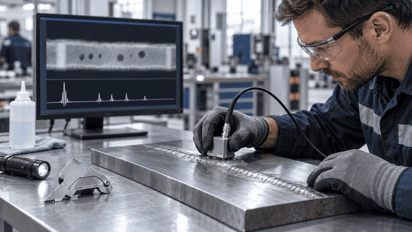
Ultrasonic testing. Use sound reflections to locate and size internal planar flaws such as incomplete fusion and cracks. Geometry, thickness, calibration, and operator qualification affect reliability.
Radiographic testing. Use X-rays or gamma rays to image density changes such as porosity and slag. It provides a record but requires radiation controls and may be less sensitive to tight planar flaws in an unfavorable orientation.
Destructive testing. For procedure qualification or production sampling, bend, tensile, fracture, macro-etch, or hardness tests can expose performance and internal quality that surface inspection cannot show.
No single method detects every defect. Select methods by material, geometry, thickness, likely flaw orientation, service risk, and governing requirements. Record the weld identifier, inspector, method, calibration, result, acceptance basis, and repair status.
How a Reliable CNC Machining Supplier Prevents and Resolves Defects
A capable CNC machining supplier treats welded fabrication as a controlled route. The team reviews the CAD model and drawing for joint access, edge preparation, datums, machining allowance, heat-sensitive dimensions, cosmetic faces, and inspection requirements. Material certificates, qualified procedures and personnel, calibrated equipment, and first-article checks establish a repeatable starting point.
Process planning should define whether critical features are machined before or after welding. Rough machining before welding can establish fit-up and leave stock for distortion correction. Finish machining after welding can restore bores, faces, and hole patterns, provided the fixture references stable datums and the repair area has enough material. In-process inspection catches misalignment before an expensive final operation locks it into the part.
When a nonconformance is found, responsible service includes containment, documented evaluation, and an approved repair plan. Identify the defect, protect remaining stock, remove it by a controlled method, verify removal where required, reweld under an approved procedure, repeat inspection, and confirm dimensions after machining. Critical cracks or repeated failures require root-cause analysis.
Clear after-sales handling matters as much as prevention. Keep photographs, inspection reports, measurement records, and lot traceability; agree whether the best remedy is rework, remake, replacement, or another approved disposition; and communicate the schedule before work proceeds. For a new project, submit the 3D model, 2D drawing, material, quantity, weld requirements, finish, tolerances, and inspection level through the CNC machining quote page so manufacturability and quality requirements can be reviewed together.
PCBgogo - Precision Custom CNC Machining
Save time and money with reliable CNC milling & turning. Get tight?tolerance custom parts, streamlined sourcing, and consistent production quality for your projects.
Get a Free Quote >
Conclusion
Welding defects are best controlled by connecting design, fit-up, welding, inspection, and CNC finishing in one process plan. Define acceptance criteria early, prevent predictable causes at the source, and choose inspection methods that can actually detect the expected flaw. That approach protects both joint integrity and the dimensions the finished assembly must hold.
Frequently Asked Questions
What are the most common welding defects
Common welding defects include cracks, porosity, undercut, overlap, burn-through, spatter, underfill, excess reinforcement, distortion, misalignment, slag inclusion, incomplete fusion, and incomplete penetration.
What is the difference between a weld discontinuity and a welding defect
A discontinuity is an interruption in the expected weld structure or profile. It is a defect only when it exceeds the acceptance criteria specified for that component, joint, or service condition.
Which welding defect is the most dangerous
Cracks are usually treated as the most serious because their sharp tips concentrate stress and they can grow under load. Actual severity still depends on location, orientation, material, loading, and the governing acceptance criteria.
Can visual inspection find internal welding defects
No. Visual testing can find surface profile problems and open discontinuities, but hidden flaws usually require ultrasonic, radiographic, or another suitable nondestructive method.
How does CNC machining help a welded assembly
CNC machining can produce repeatable joint preparation and locating features before welding, then restore critical faces, bores, holes, and datums after welding. It cannot make an unacceptable weld safe, so weld inspection must come before final acceptance.
Should a defective weld always be repaired
No. The indication must first be evaluated against the drawing, code, and engineering requirements. If repair is required, use an approved method and repeat the specified inspection after repair.





