



 日本語
日本語
 한국어
한국어

PCB Thermal Management: Complete Guide to Better Heat Dissipation
Modern electronics are becoming smaller, faster, and more powerful. The challenge is that as power density increases, so does heat generation. A PCB that performs perfectly on paper can experience reliability issues, reduced efficiency, or premature component failure if thermal management is overlooked during the design stage.
Heat is one of the most common causes of electronic failure. Effective PCB thermal management helps maintain stable operating temperatures, extend component lifespan, and improve overall system reliability. This guide explains how heat is generated in PCBs, how PCB layout affects heat dissipation, and which thermal management strategies engineers use to keep electronics running safely.
What Is PCB Thermal Management?
PCB thermal management refers to the methods used to control, transfer, and dissipate heat generated by electronic components on a printed circuit board.
Every active component converts a portion of electrical energy into heat. Power MOSFETs, voltage regulators, processors, LEDs, and power modules are among the most significant heat sources. If this heat is not efficiently transferred away from the component, junction temperatures rise and performance degrades.
The goal of thermal management in PCB design is to create a low resistance path that allows heat to move from hot components into larger conductive structures and eventually into the surrounding environment.
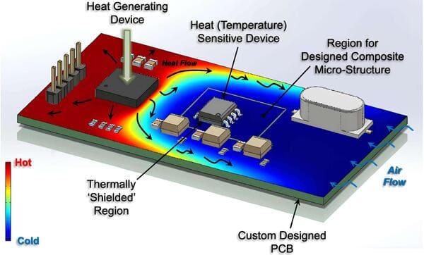
Effective thermal management typically involves a combination of:
Strategic component placement
Copper planes and copper pours
Thermal vias
Material selection
Heat sinks
Airflow optimization
Why Thermal Management in PCB Design Is Critical
Heat affects nearly every aspect of electronic performance. Even modest temperature increases can significantly reduce the lifespan of components.
The table below shows the general relationship between temperature and reliability.
| Operating Temperature | Impact on Reliability |
|---|---|
| Below 50°C | Excellent long term stability |
| 50°C to 70°C | Normal operating range |
| 70°C to 90°C | Increased component stress |
| Above 90°C | Reduced lifespan and reliability |
| Above 125°C | High risk of failure |
Poor thermal management can lead to:
Reduced component lifespan
PCB warpage
Solder joint fatigue
Signal integrity issues
Unexpected system shutdowns
Lower power efficiency
Because thermal problems often develop gradually, they can be difficult to diagnose after a product enters production. Addressing them during PCB design is far more cost effective.
Understanding why heat matters naturally leads to the next question: where should designers focus their efforts first?
How PCB Layout Affects Heat Dissipation
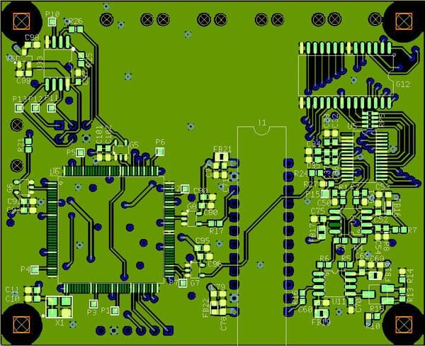
One of the most effective thermal management tools is PCB layout. Even with standard materials, a well designed layout can dramatically improve heat dissipation.
Component Placement
High power components should not be clustered together. Concentrating multiple heat sources in a small area creates thermal hotspots that are difficult to cool.
Instead:
Spread major heat generating devices across the board
Place power components near board edges when possible
Keep temperature sensitive components away from heat sources
Copper Pour Design
Copper is an excellent thermal conductor. Large copper areas help distribute heat across the PCB surface and reduce localized temperature buildup.
Designers often connect thermal pads to dedicated copper pours that function as passive heat spreaders.
Current Path Optimization
High current traces generate heat through resistive losses. Wider traces reduce resistance and lower operating temperatures.
As current increases, copper width becomes an increasingly important thermal design parameter.
Airflow Considerations
Natural and forced airflow significantly affect cooling performance.
When designing enclosures, engineers should consider:
Fan placement
Ventilation openings
Heat sink orientation
Airflow direction
Even the best PCB thermal management strategy becomes less effective if airflow is restricted.
Layout optimization alone can produce significant improvements, but material selection plays an equally important role.
PCB Materials and Their Thermal Performance
Different PCB materials conduct heat at different rates. Selecting the right substrate can dramatically improve thermal performance.
The following table compares common PCB materials used in thermal management applications.
| Material | Thermal Conductivity | Cost | Typical Applications |
|---|---|---|---|
| FR4 | Low | Low | Consumer electronics |
| Rogers | Medium | High | RF and microwave circuits |
| Aluminum Core PCB | High | Medium | LED lighting |
| Copper Core PCB | Very High | High | Power electronics |
FR4 remains the most common PCB material because of its affordability and versatility. However, high power applications often require more advanced thermal solutions.
This is where heavy copper designs become particularly valuable.
Heavy Copper PCB for Thermal Management
A heavy copper PCB uses copper thickness greater than the standard 1 oz copper found on most circuit boards. Common heavy copper designs range from 2 oz to over 20 oz copper thickness.
The additional copper provides several thermal advantages:
Improved heat spreading
Lower trace resistance
Higher current carrying capacity
Reduced hotspot formation
The table below highlights the differences.
| Feature | Standard PCB | Heavy Copper PCB |
|---|---|---|
| Copper Thickness | 1 oz typical | 2 oz to 20 oz+ |
| Current Capacity | Moderate | High |
| Thermal Conductivity | Standard | Improved |
| Power Applications | Limited | Excellent |
Heavy copper PCB for thermal management is commonly used in:
Electric vehicle systems
Industrial motor controllers
Solar power inverters
Power supplies
Battery management systems
In many high power applications, thermal management copper PCB designs provide a simpler and more reliable solution than adding larger heat sinks.
While copper thickness improves heat spreading, transferring heat between layers remains equally important.
Thermal Vias and Copper Planes
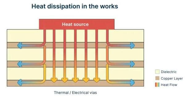
Thermal vias create vertical heat transfer pathways through the PCB stackup.
A thermal via is a plated hole positioned beneath or near a heat generating component. Heat travels through the copper plating and into internal or backside copper layers.
Good thermal via design typically includes:
Multiple vias instead of a single large via
Placement directly beneath thermal pads
Connection to large copper planes
Consistent via spacing
A common approach is using a thermal via array beneath power devices such as MOSFETs or voltage regulators.
Copper planes further improve heat dissipation by distributing thermal energy across a larger area. Together, thermal vias and copper planes form one of the most effective passive cooling methods available in PCB design.
Of course, successful thermal management involves more than individual techniques. It requires a systematic design process.
Common PCB Thermal Management Mistakes
Many overheating issues can be traced back to a handful of common design errors.
Crowding Heat Sources
Placing multiple power devices close together creates concentrated hotspots.
Insufficient Copper Area
Small copper regions limit heat spreading and increase local temperatures.
Ignoring Airflow
A well designed PCB can still overheat if enclosure airflow is inadequate.
Poor Thermal Via Placement
Vias located too far from heat sources provide limited thermal benefit.
Underestimating Thermal Resistance
Many thermal problems arise because designers focus on electrical performance while overlooking heat transfer pathways.
Avoiding these mistakes often provides greater benefits than adding expensive cooling hardware.
To further reduce risk, many engineering teams use simulation tools before building prototypes.
Thermal Simulation Tools for PCB Design
Thermal simulation helps engineers identify potential overheating issues early in the design process.
The table below compares several popular tools.
| Tool | Primary Use | Best For |
|---|---|---|
| ANSYS Icepak | Advanced thermal analysis | Complex electronics systems |
| Siemens FloTHERM | Electronics cooling simulation | High power applications |
| SolidWorks Flow Simulation | Mechanical and thermal analysis | Integrated product design |
| Altium Designer Thermal Analysis | PCB level thermal review | Early design validation |
Simulation cannot completely replace physical testing, but it significantly reduces development risk and shortens design cycles.
Once thermal analysis is complete, designers can select the most appropriate cooling strategy for their application.
Choosing the Right Thermal Strategy for Your Application
Different applications have different thermal requirements.
| Application | Recommended Thermal Strategy |
|---|---|
| LED Lighting | Aluminum core PCB |
| Automotive Electronics | Heavy copper PCB |
| Industrial Controls | Copper planes and thermal vias |
| Power Supplies | Heavy copper and heat sinks |
| Server Hardware | Multi layer thermal management |
For high current and high power designs, heavy copper PCBs often provide the most efficient balance between thermal performance and manufacturability.
When a design is ready for fabrication, choosing a manufacturer that supports standard PCB production, heavy copper PCB fabrication, and online quotation tools can simplify the transition from engineering validation to manufacturing. PCBgogo supports prototype and production PCB services, including designs that require advanced thermal management features.
FAQs
What is the best way to improve PCB thermal management?
The most effective approach combines good component placement, larger copper areas, thermal vias, and proper airflow. No single technique solves every thermal problem.
How many thermal vias should a PCB use?
The number depends on the power dissipation and available board space. Most power devices benefit from a thermal via array rather than a single via.
Is heavy copper PCB always better for heat dissipation?
Not always. Heavy copper improves heat spreading and current capacity, but factors such as layout, airflow, and material selection remain important.
What material has the highest thermal conductivity for PCB applications?
Copper core PCBs generally offer the highest thermal conductivity among common PCB materials. Aluminum core PCBs are also widely used for thermal applications.
Can thermal simulation replace physical testing?
No. Thermal simulation helps predict performance, but physical testing is still necessary to validate real world operating conditions.
Conclusion
Effective PCB thermal management combines smart layout decisions, appropriate materials, thermal vias, copper structures, and validation through simulation and testing. Addressing heat dissipation early in the design process improves reliability, extends product lifespan, and reduces costly redesigns.
For your next prototype or production project, selecting a manufacturing partner that supports heavy copper PCB fabrication and common thermal management requirements can help turn a well engineered design into a successful product.





