




 日本語
日本語
 한국어
한국어

What Are Electronic Devices and Circuits? A Complete Guide
QUICK ANSWER Electronic devices are instruments that use components such as transistors, resistors, and integrated circuits to control electrical current for processing information or converting energy. Electronic circuits are interconnected networks of these components that perform specific functions: amplification, switching, filtering, and computation. Together, they form the foundation of every modern electronic product.
Every smartphone touch, every engine control adjustment, and every medical monitor reading depends on electronic devices and circuits working together. These systems determine how information is sensed, processed, and acted upon across every industry. This guide covers what electronic devices and circuits are, the major component types and circuit classifications, how circuits are designed and tested, and how PCB manufacturing turns a design into a working product.
What Are Electronic Devices?
Electronic devices are instruments that use the controlled flow of electrical current through components to process, store, transmit, or convert information and energy. Unlike purely electrical devices that simply convert one form of energy to another (a toaster turning electricity into heat), electronic devices manipulate the electrical signal itself, amplifying it, switching it, filtering it, or converting it between analog and digital forms.
The key distinction is active control. Electronic devices contain components such as transistors and integrated circuits that can modify the behavior of electrical current in nonlinear ways. This is what enables a smartphone to run applications, a microcontroller to execute code, or a sensor to condition a weak analog signal into usable digital data. According to the IEEE Standard Dictionary of Electrical and Electronics Terms, the field of electronics is defined specifically as the branch of science and technology that deals with the motion of charge carriers in semiconductors, gases, or vacuum.
Types and Key Components of Electronic Devices
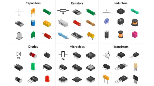
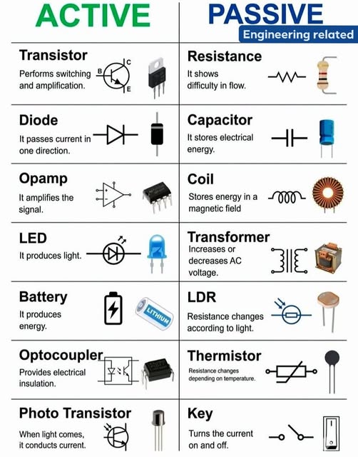
Electronic components fall into two broad groups based on whether they need an external power source to function: Passive Devices and Active Devices. Active Devices are further split into two implementation types, Semiconductor Devices and Electromechanical Devices, depending on whether they control current through a semiconductor junction or a physical mechanism. The tables below break down each category into its core components, functions, and common types.
Passive Devices
Passive devices manage the flow of electrical energy without needing an external power supply to perform their basic function, and none of them can amplify a signal.
| Component | What It Does | Common Types |
|---|---|---|
| Resistors | Limits current flow and divides voltage based on Ohm's Law (V = IR) | Carbon film, metal film, wire wound, SMD chip (0201 to 2512), variable/potentiometer |
| Capacitors | Stores energy in an electric field, blocks DC while passing AC; used for filtering, smoothing, and timing circuits | Ceramic (MLCC), electrolytic, tantalum, film |
| Inductors | Stores energy in a magnetic field and resists changes in current; used for filtering, tuning, and energy storage | Ferrite core, air core, toroidal, fixed and variable |
| Transformers | Transfers electrical energy between circuits through electromagnetic induction, stepping voltage up or down | Step-up, step-down, isolation transformer |
Active Devices
Active devices require an external power source and can control, amplify, or switch the flow of current, rather than simply managing it as passive devices do. Depending on the mechanism used to achieve this control, active devices fall into two groups: semiconductor devices that switch current electronically with no moving parts, and electromechanical devices that use a physical or magnetic element to make or break a connection.
1. Semiconductor Devices
Semiconductor devices are active components built from materials such as silicon or germanium, whose conductivity can be precisely controlled electronically. They form the basis of nearly all modern signal processing and computing hardware.
| Component | What It Does | Common Types |
|---|---|---|
| Diodes | Allows current to flow in one direction only; used for rectification, voltage regulation, and signal demodulation | Rectifier, Zener, Schottky, LED |
| Transistors | A three-terminal device used as an electronic switch or amplifier; controls current between two terminals by varying the voltage or current at the third | BJT (NPN/PNP), MOSFET, IGBT |
| Thyristors | A multi-layer semiconductor switch that latches on and keeps conducting until current drops below a holding threshold; used for power control | SCR (silicon-controlled rectifier), TRIAC |
| Integrated Circuits (ICs) | Combines many transistors, resistors, and capacitors on a single chip to perform a complete function | Microcontrollers, microprocessors, op-amps, memory, logic ICs |
2. Electromechanical Devices
Electromechanical devices are active components that use a mechanical or magnetic element, rather than a semiconductor junction, to open, close, or move a circuit connection.
| Component | What It Does | Common Types |
|---|---|---|
| Relays | Uses an electromagnet to mechanically open or close a separate, often higher-power, circuit | Electromagnetic relay, reed relay, solid-state relay |
| Switches | Manually or mechanically makes or breaks a circuit connection | Push-button, toggle, DIP, slide |
| Motors | Converts electrical energy into rotational or linear mechanical motion | DC motor, stepper motor, servo motor |
| Solenoids | Converts electrical current into linear mechanical motion using an electromagnetic coil and plunger | Push-type, pull-type, latching solenoid |
These components do not function in isolation. They are connected on printed circuit boards (PCBs) to form the circuits that give electronic devices their operational capability.
What Are Electronic Circuits?
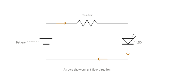
Electronic circuits are closed-loop networks of interconnected electronic components through which current flows along designed paths to perform a specific function. A circuit becomes electronic rather than simply electrical when it includes at least one active component (a transistor, diode, or integrated circuit) that can control, amplify, or switch the flow of current in a non-linear way.
Every electronic circuit can be analyzed through two complementary frameworks: the physical interconnection of components (the schematic and PCB layout) and the abstract flow of signals through the network (the circuit function). A voltage regulator circuit, for example, consists physically of a reference diode, error amplifier, pass transistor, and feedback resistors on a PCB, while functionally it maintains a constant output voltage regardless of input variation or load changes. Ohm's Law (V = IR) and Kirchhoff's Current and Voltage Laws provide the mathematical foundation for analyzing any circuit, from a single-transistor amplifier to a multi-layer server motherboard.
Types of Electronic Circuits
Electronic circuits fall into several broad categories, each optimized for different signal types and application requirements. The classification is based on how the circuit processes its input signals. The table below compares the four main circuit types across their defining characteristics.
| Circuit Type | Signal Type | Key Components | Typical Applications | Key Design Consideration |
|---|---|---|---|---|
| Analog | Continuous voltage/current | Op-amps, transistors, resistors, capacitors | Audio amplifiers, sensor front-ends, RF receivers, power management | Noise, linearity, bandwidth, temperature drift |
| Digital | Discrete logic levels (0/1) | Logic gates, flip-flops, microprocessors, FPGAs | Computing, control systems, digital communication, signal processing | Timing closure, power consumption, fan-out, setup/hold margins |
| Mixed-Signal | Both analog and digital | ADCs, DACs, mixed-signal ICs, microcontrollers | Data acquisition systems, smartphones, IoT devices, motor control | Noise isolation between domains, grounding strategy, supply decoupling |
| Power | High current/voltage | MOSFETs, IGBTs, inductors, transformers, diodes | Power supplies (SMPS), motor drives, inverters, battery chargers | Thermal management, efficiency, safety isolation, component derating |
Designing Electronic Circuits
Electronic circuit design follows a structured workflow that moves from abstract requirements to a physical, manufacturable board. The process integrates component selection, schematic capture, simulation, and PCB layout into a single discipline.
The design flow begins with requirements definition: specifying input signals, desired output behavior, power constraints, size limits, and environmental conditions. From these requirements, the designer selects a circuit topology: a common-emitter amplifier for gain, a buck converter for step-down regulation, or a microcontroller plus peripherals for programmable logic. Component values are then calculated or simulated using tools such as SPICE (Simulation Program with Integrated Circuit Emphasis), which can model DC operating points, AC frequency response, and transient behavior before any hardware is built.
Schematic capture translates the circuit concept into a formal, tool-readable netlist that documents every component and connection. From the netlist, PCB layout begins: placing components on the board, routing copper traces between them, and defining the layer stack-up. Signal integrity becomes critical at higher frequencies. Traces become transmission lines, and impedance matching, controlled trace lengths, and return path continuity must be maintained. The IPC-2221 standard provides design guidelines for trace width, spacing, and current-carrying capacity that are referenced throughout the industry.
Thermal management is a design factor that must be addressed during layout, not after. Components that dissipate significant power require copper pours for heat spreading, thermal vias to conduct heat into internal planes, and sometimes dedicated heatsinks. A 1W surface-mount regulator without adequate copper area can reach junction temperatures exceeding 125 degrees Celsius, degrading reliability or triggering thermal shutdown.
Once the layout is complete, the design data (Gerber files, drill files, BOM, and assembly drawings) is released for fabrication. This is where the design transitions from concept to physical reality.
PCB Manufacturing and Assembly: How PCBgogo Supports Electronic Design
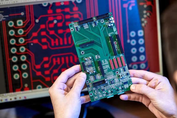
After the schematic is verified and the layout passes design rule checks, the next step is fabrication. The PCB manufacturer's capabilities directly determine whether a design can be built as intended. Trace geometries, layer registration, material quality, and assembly precision all affect whether the finished board matches the designer's specifications.
PCBGOGO CAPABILITIES To maintain stable yield in dense, high-layer PCB builds, PCBgogo uses copper-clad laminates from Shengyi and Kingboard, securing PCB quality starting from the base material. Advanced automated lamination equipment then holds precise layer alignment and pressure control through builds up to 40 layers, preventing delamination and warpage as layer count increases. Each board also passes multiple rounds of AOI and 3D X-ray inspection to catch common PCB defects. For assembly, PCBgogo runs SMT and through-hole lines supporting both leaded and lead-free processes, backed by long-term partnerships with multiple component suppliers that keep parts in stock.
Rigid FR-4 PCB
1 to 40 layers, TG130 to TG170 material grades
Trace/space as fine as 2mil on inner layers
Minimum hole diameter down to 0.1mm, max aspect ratio 12:1
Board thickness from 0.2mm to 6.0mm; panels up to 600 x 1200mm
HDI builds available on the same line (1 to 3 build-up steps, embedded passives)
Surface finishes: HASL, ENIG, OSP, immersion silver, hard gold, ENEPIG
Flex PCB
1, 2, 4, 6, or 8 layers, PI or PET base
Thickness from 0.08mm to 0.4mm+
Copper weight 0.5oz to 2oz
Minimum pad diameter 0.3mm
Panels up to 4000 x 240mm (single layer)
Surface finishes: ENIG, OSP, immersion tin, immersion silver
Lead time: 5 to 7 days
Metal-Core PCB (Aluminum)
1, 2, 4, 6, or 8 layers
Thermal conductivity from 1W to 12W/mK
Board thickness 0.8mm to 2.0mm
Trace/space 4mil, copper weight up to 4oz
Panels up to 600 x 1200mm
Surface finishes: HASL, ENIG, OSP, hard gold, ENEPIG, immersion silver
Certified to ISO 9001, UL, RoHS, REACH
PCBA / Assembly
Board size from 50 x 50mm to 510 x 460mm
Placement accuracy ±0.035mm (Cpk ≥ 1.0)
Smallest package handled: 01005 (0.4mm x 0.2mm)
BGA support down to 0.14mm ball diameter / 0.2mm pitch
SMT, through-hole (DIP), and mixed assembly
Full or partial turnkey component sourcing, or customer-supplied parts
Inspected to IPC-A-610; visual, AOI, and X-ray inspection on BGA joints
24-hour rush service available; prototype orders typically 3 to 4 days
Free stencils, framed or frameless, come standard with every assembly order. Rigid-flex boards and RF laminates like Rogers are also available for specialized designs. Reach out to PCBgogo for exact specs on those builds.
For designers moving from prototype to production, having a manufacturer that can handle rigid, flex, HDI, and assembled boards under a single quality system reduces the number of variables in the supply chain. More information about specific capabilities is available at PCBgogo.
Testing Electronic Devices
Testing electronic devices verifies that a circuit functions as designed and meets performance specifications. The testing process spans the entire development cycle, from initial breadboard debugging through production-line automated verification.
Digital Multimeter (DMM): Measures DC and AC voltage, current, resistance, and continuity. It is the first tool reached for when a circuit is not behaving as expected. Modern DMMs offer 4.5 to 6.5 digits of resolution, with measurement accuracy in the range of 0.01% to 0.5% depending on the range and function.
Oscilloscope: Captures and displays voltage waveforms over time, revealing signal shape, amplitude, frequency, noise, and timing relationships between multiple channels. Digital storage oscilloscopes (DSOs) with bandwidths from 50MHz to several GHz let designers visualize everything from slow sensor outputs to high-speed serial data eyes.
Function Generator: Produces controlled test signals (sine, square, triangle, ramp, and user-defined arbitrary waveforms) for stimulating circuits during testing. Pairing a function generator with an oscilloscope enables frequency response analysis of filters, amplifiers, and control loops.
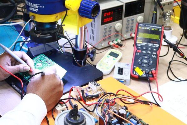
Beyond bench instruments, production testing relies on automated systems: flying probe testers verify continuity and isolation on bare PCBs, in-circuit testers (ICT) check individual component values on assembled boards, and functional test fixtures run the completed device through its operational modes. IEEE 1149.1 boundary-scan (JTAG) testing provides access to individual IC pins for fault detection without physical probe access, which is particularly valuable on dense boards with limited test points.
Applications of Electronic Devices and Circuits
Electronic devices and circuits are applied across every sector where information must be sensed, processed, communicated, or acted upon. The specific circuit requirements (precision, speed, power, ruggedness) vary dramatically by application.
Consumer electronics: Smartphones, laptops, televisions, and wearable devices rely on densely integrated digital and mixed-signal circuits. The main logic board in a modern smartphone packs an application processor, DRAM, flash storage, power management ICs, and multiple RF transceivers onto a 10 to 14-layer HDI PCB, with component placement densities measured in thousands of parts per square inch.
Industrial automation: PLCs (programmable logic controllers), motor drives, and sensor networks use robust circuits designed for 24V industrial logic levels, high electrical noise environments, and extended temperature ranges. Optocouplers and isolated gate drivers provide galvanic separation between low-voltage control electronics and high-power switching circuits, protecting both the controller and the operator.
Medical devices: Patient monitors, infusion pumps, and imaging equipment demand circuits with low noise, high reliability, and compliance with IEC 60601 safety standards. The signal chain from a biopotential electrode to a readable ECG waveform involves a differential instrumentation amplifier with high common-mode rejection, followed by filtering, digitization, and software processing. Each stage contributes to measurement accuracy that can guide clinical decisions.
Automotive electronics: Engine control units, ADAS (advanced driver assistance systems), and battery management systems for electric vehicles operate in harsh thermal and vibration environments. Automotive-qualified components carry AEC-Q100 certification, and PCB materials for under-hood applications must withstand continuous temperatures above 125 degrees Celsius. The shift toward electric and autonomous vehicles is driving rapid growth in power electronics and high-speed sensor processing circuits.
Telecommunications: Base stations, routers, and optical networking equipment process high-frequency signals where PCB trace geometry, dielectric constant, and loss tangent directly affect system performance. 5G infrastructure operating at millimeter-wave frequencies (24GHz and above) requires specialized low-loss PCB materials such as Rogers laminates, with impedance tolerances held to within 5% across the full signal path.
Each of these applications places different demands on the underlying electronic circuits, yet they all depend on the same fundamental principles of component behavior, signal processing, and physical interconnection.
Conclusion
Electronic devices and circuits are the enabling technology behind every piece of modern electronics, from the simplest LED driver to the most advanced multi-core processor. Understanding the component types, circuit classifications, design workflow, and manufacturing options covered in this guide provides a solid foundation for anyone working with electronics. Whether you are prototyping a new design on a breadboard or preparing to release a product into production, the principles and practices remain the same: design intentionally, verify thoroughly, and partner with a manufacturer whose capabilities align with your design requirements.
FAQ
What is the difference between electrical and electronic circuits?
An electrical circuit conducts current to deliver power (such as a lighting circuit or a heating element), while an electronic circuit uses active components like transistors to process information carried by the current. The presence of semiconductor devices that can amplify, switch, or modify signals defines the boundary between the two fields.
What are the most common types of electronic components?
Resistors, capacitors, inductors, diodes, and transistors are the five most common discrete electronic components. Integrated circuits, which package complete functional blocks on a single chip, are the most common components by function despite each IC counting as a single part on the bill of materials.
How do I choose the right PCB type for my electronic design?
The choice depends on your design's physical, electrical, and environmental requirements. Use rigid FR-4 for most general-purpose designs, flex or rigid-flex when the board must bend or fit into a non-planar enclosure, HDI for high-density designs with fine-pitch BGAs, and metal-core boards when heat dissipation is the primary constraint. Consulting with your manufacturer early in the design process helps avoid specifying a board type that adds cost without benefit.
What is the difference between analog and digital circuits?
Analog circuits process continuously varying signals and are sensitive to exact voltage levels. Digital circuits process binary signals (HIGH/LOW) and tolerate a defined voltage range for each logic state. Mixed-signal designs often use analog circuits at the physical interface (sensors, amplifiers, ADCs) and digital circuits for computation and control.
What tools are needed to test electronic circuits?
A digital multimeter for voltage, current, and continuity measurements is the essential starting point. An oscilloscope for waveform visualization and a function generator for stimulus signals cover the next tier of testing needs. For production environments, automated test equipment (ATE), flying probe testers, and boundary-scan tools add throughput and fault coverage.
What are HDI PCBs and when should they be used?
HDI (High Density Interconnect) PCBs use microvias (laser-drilled vias typically under 0.15mm diameter), fine traces and spaces, and sequential lamination to achieve higher routing density than conventional through-hole PCBs. They are used when component pin density, BGA pitch, or board size constraints make conventional routing impractical. This is common in smartphones, wearables, and compact IoT devices.





