
 日本語
日本語
 한국어
한국어

Blind Hole Machining: Design Rules and Process Guide
QUICK ANSWER Blind hole machining creates a hole that stops at a controlled depth instead of passing through a part. Reliable results depend on defining full diameter depth, allowing for the drill point, evacuating chips, controlling heat, and leaving clearance for threads. The best process may combine drilling, reaming, boring, milling, tapping, or thread milling.
What Is Blind Hole Machining?
Blind hole machining is the controlled production of a closed-end hole whose depth, diameter, bottom shape, location, and optional thread must meet the part drawing. The feature may hold a screw, dowel, bearing, spring, sensor, fluid passage, or hidden fastener while preserving the opposite wall. It is common in housings, manifolds, fixtures, electronic enclosures, and structural components.
The closed bottom creates the central process problem: chips and heat have only one exit. A conventional drill also leaves a conical point below the full diameter portion. If design and CAM use different depth references, the part can be underthreaded or broken through.
How Is a Blind Hole Different From a Through Hole?
A blind hole stops inside the workpiece, while a through hole opens on the opposite side. That simple geometric difference changes chip flow, coolant access, depth control, tooling, cycle time, and inspection.
| Decision factor | Blind hole | Through hole |
|---|---|---|
| Chip path | Chips must return through the flutes | Chips may exit from either end |
| Depth risk | Too much travel can break the remaining wall | Breakthrough is intentional |
| Bottom geometry | Conical, radiused, or flat as specified | No closed bottom |
| Threading | Needs chip and runout clearance | Tap can pass through the part |
| Inspection | Depth and floor shape require access planning | Both ends may be accessible |
When either geometry works, a through hole is usually easier to manufacture. Use a blind hole when it protects a sealing face, hides a fastener, or preserves an exterior wall.
How Does the Blind Hole Machining Process Work?
The blind hole machining process converts a functional depth requirement into a controlled sequence of roughing, chip removal, finishing, and verification. The exact route depends on material, diameter, depth to diameter ratio, bottom shape, tolerance, surface finish, and thread requirement.
Define the depth datum: State whether depth ends at the full diameter shoulder or drill tip. Autodesk Fusion distinguishes these references and supports tip compensation.
Start accurately: A spot drill or self-centering drill limits walking. Angled or rough faces may need a milled pad.
Control chips: Autodesk documents chip breaking above roughly three to four tool diameters and full retract deep drilling when chips or coolant access demand it. Follow the drill maker's data.
Finish selectively: Reaming refines size and finish, boring corrects geometry, and circular milling can create larger or flat bottom features.
Clean and inspect: Remove chips before confirming diameter, depth, position, floor condition, and remaining wall against the drawing.
The theoretical drill point height equals D divided by two times tan(A divided by two). It is about 0.30D for a 118 degree point and 0.21D for a 135 degree point, but critical work should use the actual tool model.
What Makes Blind Hole Tapping Reliable?
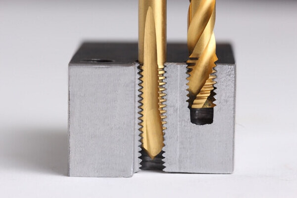
Reliable blind hole tapping needs extra drilled depth for the tap chamfer, chip space, and thread runout. Making thread depth equal to drill depth invites incomplete threads or a broken tap.
Spiral flute tap: It carries chips toward the opening and is common for blind holes in chip forming materials.
Form tap: It displaces ductile material without creating chips, but needs a different pilot diameter.
Thread milling: An interpolating cutter controls thread diameter without trapping a full length tap in the part.
Bottoming tap: Its short chamfer extends usable thread closer to the floor, but clearance is still required.
Specify minimum full thread depth and a safe maximum drill depth where wall thickness is critical. Manufacturing can then choose the method without risking breakthrough.
Which Design Rules Reduce Blind Hole Cost and Risk?
Good blind hole design separates functional requirements from unnecessary precision, then gives the cutting tool room to work. The largest savings often come from changing the feature before CAM programming begins.
Standard size and depth: Use standard drills and keep the hole as shallow as function allows. Higher depth to diameter ratios make tools and chip removal less forgiving.
Explicit depth convention: Dimension usable cylindrical depth and state whether the floor may be conical or must be flat.
Real thread clearance: Separate required thread engagement from drilled depth, including chamfer, runout, and chip space.
Selective tolerances: Tighten diameter, position, and finish only where fit or sealing requires it. Precision can add finishing and inspection steps.
Tool access and wall support: Prefer a perpendicular entry, avoid deep holes beside thin walls, and leave holder clearance.
Release a STEP file and drawing with material, quantity, thread class, finish, critical dimensions, and inspection needs.
How Do Materials Change Blind Hole Drilling Strategy?
Material behavior changes how blind hole machining manages chips, heat, edge wear, and dimensional stability. Generic speed and feed values are poor substitutes for tool manufacturer data and a validated process on the actual machine.
Aluminum: Long chips may crowd flutes or weld to the edge, so sharp geometry and chip breaking matter.
Stainless steel: Rubbing can work harden the surface. Maintain stable engagement, feed, and coolant.
Titanium and nickel alloys: Concentrated heat and tool wear demand rigid tooling and application specific coolant delivery.
Engineering plastics: Heat can cause melting or elastic recovery, so measure after the part stabilizes.
A smaller peck is not automatically safer. Excessive retracts add time and may recut chips, so follow the tool supplier's cycle guidance.
How Can You Troubleshoot Blind Hole Defects?
Blind hole defects are best diagnosed by separating depth, diameter, position, wall finish, floor finish, and thread quality. Changing several parameters at once hides the cause and makes the process difficult to repeat.
Shallow full diameter depth: Check the CAM depth reference, tool offset, point angle, and wear.
Packed chips or scored walls: Review chip shape, flute loading, coolant, retract distance, and chip recutting.
Oversized or tapered bore: Inspect runout, holder condition, lip balance, deflection, and entry surface.
Poor floor finish: Match the floor to the tool. A twist drill cannot create a flat floor.
Broken tap: Check drill depth, pilot size, chips, alignment, torque, work hardening, and lubrication.
Match inspection to the defect. Depth probes verify accessible floors, pin or bore gauges check size, and CMM or optical methods confirm location. Critical hidden geometry may need a dedicated probe or validated process plan.
How PCBgogo Supports CNC Machined Electronics Projects
PCBgogo provides CNC machining services for custom parts with blind holes, threaded features, controlled depths, and other precision geometries. From early prototypes to repeat production, the goal is to ensure every blind hole performs as intended, with the right depth, diameter, threading, surface quality, and fit for assembly.
Manufacturability review: PCBgogo reviews the 3D model and engineering drawing before production, helping identify risks such as excessive depth-to-diameter ratios, insufficient bottom clearance, thin remaining walls, restricted tool access, or ambiguous depth callouts.
Process planning for blind holes: Depending on the material and feature requirements, the machining strategy may include controlled drilling, chip-clearing cycles, tapping, thread milling, reaming, boring, or flat-bottom machining. The process is selected around hole accuracy, chip evacuation, tool stability, and the required bottom geometry.
Drawing-based precision control: Critical dimensions such as hole diameter, full-diameter depth, position, thread depth, and remaining wall thickness can be reviewed against the customer’s drawing and inspection requirements.
Support from prototype to production: PCBgogo helps customers validate part geometry during prototyping and maintain consistent manufacturing requirements as projects move toward repeat orders.
Have a CNC part with blind holes or difficult internal threads? Send us your 3D CAD model, 2D drawing, material, surface-finish requirements, quantity, and critical tolerances. The CNC team can review manufacturability, identify potential cost or production risks, and provide a project-specific quotation.
Frequently Asked Questions About Blind Hole Machining
How deep can a blind hole be machined?
There is no universal maximum because capability depends on diameter, material, tooling, coolant, rigidity, and geometry. Autodesk identifies simple drilling below about three tool diameters and chip breaking or deep drilling for deeper conditions, but supplier data should set the limit.
Should blind hole depth include the drill point?
The drawing should state whether depth refers to the full diameter portion or the deepest drill tip. For functional fits and threads, full diameter depth is usually the more useful requirement, with point depth added as manufacturing allowance.
Can a blind hole have a flat bottom?
Yes, but a standard twist drill produces a conical floor. A flat bottom drill, end mill, counterbore, or circular milling process is required, and the designer should specify the floor flatness or finish only when function demands it.
What is the best tap for a blind hole?
A spiral flute tap is a common choice because it directs chips toward the opening. Form tapping or thread milling may be better for compatible materials and applications, while a bottoming tap helps extend the thread closer to the floor when enough clearance remains.
How should a blind hole be shown on a drawing?
Call out diameter, depth reference, thread size, minimum full thread depth, bottom shape, location, and critical tolerances. Add a no-breakthrough note when the remaining wall matters.
Build the Requirement Around the Usable Hole
Successful blind hole machining begins with one unambiguous question: what usable diameter, depth, thread, and bottom condition does the assembly need? Define that function, leave room for the drill point and threading process, choose chip control for the real material, and verify the feature with an inspection method that can reach it. For electronics projects, PCBgogo can review CNC-machined enclosure needs together with PCB and assembly interfaces before quotation.





