



 日本語
 한국어

Types of Holes in CNC Machining: Design and Process Guide
A CNC hole is not just an empty cylinder. Hole type determines the machining method, chip evacuation, inspection approach, hardware choice, and cost. Start by defining whether the hole is through or blind, then specify any thread, seating feature, tolerance, and positional requirement.
Which Hole Types Are Most Common in CNC Parts?
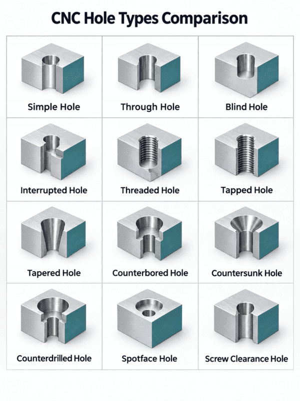
The most common CNC hole types are through holes, blind holes, threaded holes, clearance holes, counterbores, countersinks, spotfaces, and reamed holes. Each is defined by its geometry and intended function, not simply by diameter.
Through hole: Passes fully through the part and is the simplest option for clearance, drainage, wiring, or a through fastener.
Blind hole: Stops within the material and needs a depth callout. A standard drill leaves a conical bottom, which must be allowed for in the design.
Tapped hole: Contains an internal thread for a screw. Thread class and usable thread depth matter more than nominal drill diameter.
Counterbore: Provides a flat bottom recess for a socket head screw or bolt head.
Countersink: Produces a conical seat for a flat head fastener, commonly specified by diameter and included angle.
Spotface: Creates a shallow flat seating surface on a rough or curved face.
Reamed hole: Uses a light finishing operation after drilling to improve diameter accuracy, roundness, and surface finish. It is commonly used for dowels, locating pins, and precision-fit components. Reaming cannot compensate for a badly positioned or poorly prepared pilot hole.
What Drives Hole Design and Machining Cost?
Hole cost rises when feature access, tolerance, depth, or inspection becomes more demanding.
Depth to diameter ratio: Deep holes make chip evacuation and tool deflection more difficult.
Tolerance and fit: A clearance hole can often be drilled, while a tight pin or bearing fit may need reaming, boring, or grinding.
Thread engagement: Blind threaded holes need clearance below the full thread because taps and thread mills cannot form threads to the exact bottom.
Edge distance: Holes too close to an edge can break out, distort, or leave insufficient material for a load bearing fastener.
Datum scheme: Hole position should be measured from functional surfaces, not from an arbitrary chain of dimensions.
When a hole combines tight position, a precision fit, and adjacent milled features, PCBgogo's CNC milling and turning capability supports a drawing review before machining. The useful output is a process route that protects the functional datum through drilling, reaming, and final inspection.
ISO 286 provides the common system for limits and fits of holes and shafts. It does not select the manufacturing process for you, but it gives designers a shared language for mating parts.
PCBgogo - Precision Custom CNC Machining
Save time and money with reliable CNC milling & turning. Get tight?tolerance custom parts, streamlined sourcing, and consistent production quality for your projects.
Get a Free Quote >
How Should a Hole Be Called Out on a Drawing?
A complete hole callout identifies diameter, depth or through condition, thread or seat geometry, and any required tolerance. A drawing should also show positional tolerance where assembly function demands it. Avoid an unnecessarily tight diameter tolerance when the real requirement is only bolt clearance.
What Failures Should Designers Prevent?
Hole problems often come from an ambiguous drawing rather than poor machining. Common failures include a blind hole that is too shallow for the fastener, a counterbore with insufficient wall thickness, a thread with no lead in chamfer, and a tight reamed hole placed after heat treatment without a finishing plan. A practical drawing leaves room for drill point geometry, deburring, and inspection access.
Where Is This CNC Approach Used?
Applications for types of holes differ by load, environment, and production quantity.
Bolt clearance holes: Bolt clearance holes use metals and engineering plastics selected for the complete component where geometry, service load, and production volume justify CNC processing. The drawing should isolate functional dimensions so inspection effort follows the part's real job.
Dowel locating holes: Dowel locating holes use metals and engineering plastics selected for the complete component where geometry, service load, and production volume justify CNC processing. The drawing should isolate functional dimensions so inspection effort follows the part's real job.
Bearing bores: Bearing bores use metals and engineering plastics selected for the complete component where geometry, service load, and production volume justify CNC processing. The drawing should isolate functional dimensions so inspection effort follows the part's real job.
Fluid passages: Fluid passages use metals and engineering plastics selected for the complete component where geometry, service load, and production volume justify CNC processing. The drawing should isolate functional dimensions so inspection effort follows the part's real job.
Threaded mounting holes: Threaded mounting holes use metals and engineering plastics selected for the complete component where geometry, service load, and production volume justify CNC processing. The drawing should isolate functional dimensions so inspection effort follows the part's real job.
What Should Engineers Compare Before Choosing?
The table compares practical options associated with types of holes.
| Option | Key characteristic | Machining or process | Typical use |
|---|---|---|---|
| Through hole | Drilling | Clearance or passage | Low |
| Blind hole | Drilling | Internal feature | Medium |
| Reamed hole | Drill and ream | Precision pin fit | Medium |
| Counterbore | Drill and counterbore | Bolt head seat | Medium |
What Drives a Manufacturable Design?
A manufacturable types of holes specification connects function to process capability.
Functional requirement: Define what types of holes must achieve before selecting a grade, tool, or process. Load, motion, environment, and mating components should translate into measurable drawing requirements.
Material condition: Record the incoming and final condition of metals and engineering plastics selected for the complete component. Hardness and heat treatment can change cutting behavior, distortion risk, and the operation that should create the final dimension.
Datum strategy: Build the setup around diameter, depth, location, thread, seat geometry, and bottom clearance. Functional datums reduce accumulated error and make the inspection report easier to compare with assembly needs.
Tool access: Review reach, corner radius, chip evacuation, and holder clearance before programming drilling, boring, reaming, tapping, counterboring, and countersinking. Better access usually reduces setup count and avoids unnecessarily long tools.
Tolerance allocation: Apply close limits only to features that control fit, sealing, location, or motion. General surfaces can use a broader standard tolerance without weakening performance.
Workholding: Clamp against stable reference surfaces and support flexible areas near the cut. The setup must resist cutting force without temporarily bending the workpiece.
Surface finish: Specify roughness where friction, sealing, fatigue, or appearance requires it. A low Ra value on every surface increases cycle time and inspection with little functional return.
What Workflow Reduces Rework?
A reliable types of holes workflow closes decisions in a deliberate order.
Confirm the material specification and delivery condition for metals and engineering plastics selected for the complete component.
Mark diameter, depth, location, thread, seat geometry, and bottom clearance as critical, reference, or general features on the drawing.
Choose a setup sequence for drilling, boring, reaming, tapping, counterboring, and countersinking that preserves the same functional datums.
Review the main process risks, especially chip packing, drill wander, breakout, burrs, and ambiguous callouts, before approving the first article.
Define inspection records for diameter, depth, position, thread class, and seat geometry and agree on sampling before production.
Which Quality Controls Belong in the Plan?
Quality control for types of holes is a stack of material, process, and dimensional checks.
Incoming control: Verify material identity and condition before machining. This prevents a correct program from producing parts in the wrong alloy or hardness.
First article inspection: Measure the complete first setup before releasing the batch. The result confirms both the program and the datum transfer strategy.
In process checks: Monitor tool wear and the dimensions most sensitive to chip packing, drill wander, breakout, burrs, and ambiguous callouts. Scheduled checks are more reliable than waiting for the final inspection to reveal drift
FAQs
What is the difference between a counterbore and a countersink?
A counterbore is a cylindrical, flat bottom recess. A countersink is a conical recess for a flat head screw.
When should a hole be reamed?
Ream a hole when its size, roundness, and surface finish are important for a pin, dowel, or controlled fit. Drill the hole first with suitable stock allowance.
Are blind holes more expensive than through holes?
They can be, because depth control and chip evacuation are harder. The cost difference depends on material, depth, tolerance, and the number of features.
The most economical hole is the one whose geometry and tolerance match its real function. Specify the finished feature, then select the process that can produce it reliably.





