
 日本語
日本語
 한국어
한국어

Text Milling: A Practical Guide to CNC Lettering and Engraving
Text milling turns names, serial numbers, warnings, scales, and logos into permanent features of a manufactured part. Instead of applying ink or a label, a rotating cutter follows a programmed path and removes material to form each character. The result can survive handling, cleaning, heat, and abrasion that would quickly damage a surface-only mark. This guide explains how CNC text milling works, which design choices control readability and cost, and what to include in your manufacturing files before requesting a quote.
What Is Text Milling?
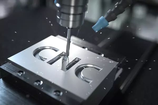
Text milling is a CNC machining operation used to cut letters, numbers, symbols, or simple graphics into a workpiece. It is often described as CNC engraving or CNC lettering, although the terms are not always identical. Engraving may include decorative lines and artwork, while text milling focuses on legible information. Both use CAD geometry, CAM-generated toolpaths, and a controlled cutting tool.
Most applications use recessed text because it removes relatively little material and can be machined during the same setup as other part features. Raised text is also possible, but the machine must clear the material around every character, increasing cycle time. Typical uses include part numbers, serial codes, control-panel labels, fixture positions, safety warnings, product branding, and calibration marks.
How CNC Text Milling Works
A reliable result begins before the spindle starts. The manufacturer converts the text into vector geometry, creates a centerline, contour, or pocket toolpath, and machines it at a controlled speed and depth. Deburring, coating, or ink filling may follow when stronger contrast is needed.
1. Create clear CAD geometry
Place the exact text in the 3D model or a dimensioned drawing. Define its font, orientation, and wording. Convert special fonts or logos to curves to prevent substitution between software systems.
2. Choose a toolpath strategy
Centerline engraving follows the middle of each stroke and suits small identification marks. Contour milling traces the outlines for bolder lettering, while pocket milling clears each letter for a flat-bottomed recess. More cleared area means a longer cycle.
3. Match the cutter to the detail
A V-bit produces sharp strokes for fine lettering. Small flat end mills create consistent grooves for larger outlined or filled characters, while ball end mills leave a rounded groove. Because no tool can reproduce an internal corner smaller than its effective radius, cutter access must guide the font and scale.
Design Rules for Readable, Cost-Effective Text
Good text milling is a design-for-manufacturing problem. Screen-perfect lettering can lose counters, corners, or spacing once a physical cutter follows it. Use these rules as starting points and confirm final limits with the manufacturer.
Use simple fonts and generous strokes
Sans-serif or single-line fonts are usually safest because uniform strokes preserve clarity at small sizes. Serif, script, and stylized fonts may contain features smaller than the cutter. If a brand font is mandatory, enlarge it or simplify the vector outline.
Specify size, stroke width, spacing, and depth
Character height alone does not define machinability. State the minimum stroke width and leave enough spacing to avoid fragile walls. Many general industrial markings start around 2.5-4 mm high and 0.2-0.5 mm deep, but these are planning ranges, not universal limits. Smaller or deeper text increases process risk and cost.
Protect edges and structural areas
Keep lettering away from thin walls, sealing surfaces, bearing seats, and highly stressed regions. Deep grooves can concentrate stress, while text near an edge may leave a weak lip. Dimension from functional datums when alignment matters.
Design for contrast, not depth alone
Deeper characters are not automatically easier to read; contrast often matters more. Cutting through colored anodizing can reveal bright aluminum, while stainless steel may need ink fill or a brushed background. Decide the treatment sequence early because engraving after coating exposes the base material.
Material and Tooling Considerations
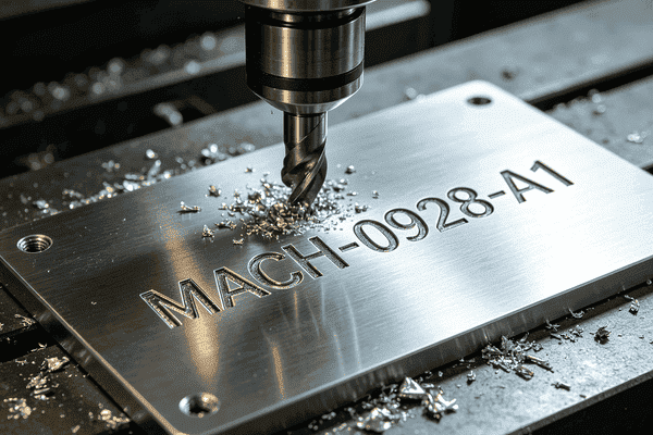
Aluminum suits CNC text milling because it cuts easily and supports fine detail. Brass creates attractive decorative lettering, while stainless steel needs conservative parameters and careful tool-wear control. On hard metals, larger characters are often more reliable than fragile micro-tools.
Acrylic, ABS, POM, and other plastics can produce clean lettering, but heat may melt or smear the groove. Sharp cutters, suitable chip load, and air blast remove heat and chips. Very soft plastics may deform instead of holding a crisp line.
Tool runout is especially visible in small text. Stable workholding, a clean collet, short tool overhang, shallow step-downs, and toolpath simulation improve consistency. Inspect a first article before releasing critical production markings.
Text Milling vs. Other Marking Methods
| Method | Durability | Best fit | Main trade-off |
|---|---|---|---|
| Text milling | Permanent recessed feature | Depth, tactile marks, alignment with machined features | Slower for complex or high-volume text |
| Laser marking | High, usually surface-level | Fine detail and fast variable data | Limited physical depth |
| Printing/labels | Low to moderate | Color, low cost, easy updates | Can fade, peel, or abrade |
| Stamping | Permanent | Simple marks on robust parts | Tooling, deformation, and lower flexibility |
Choose CNC text milling when the mark needs physical depth, precise alignment with machined features, or strong abrasion resistance. Laser marking is faster for many fine, surface-level identifiers. Printing and labels add color at low initial cost, while stamping is permanent but less flexible. Let the service environment, volume, geometry, and appearance determine the method.
Common Problems and How to Prevent Them
Closed counters and distorted letters
If the cutter cannot enter the inside of an A, R, B, or small numeral, the counter closes and the character becomes hard to recognize. Increase the text size, widen the stroke, simplify the font, or use a smaller tool after confirming that the process can hold it reliably.
Burrs, rough edges, and inconsistent width
These defects commonly point to a worn tool, excess runout, poor chip evacuation, vibration, or an unsuitable feed and speed combination. A light finishing pass or controlled deburring can help, but process stability should be corrected first so the letters remain dimensionally consistent.
Uneven depth on large or curved faces
A shallow engraving magnifies any error in part flatness, fixturing, or work-coordinate setup. Surface probing can compensate on some flat panels. Curved or angled surfaces may need indexed multi-axis machining, a projected toolpath, or a dedicated fixture that keeps the tool correctly oriented.
Unexpected cost
Intricate fonts, deep pockets, long messages, many tool changes, individual serial data, and post-machining color fill all add time. Reduce cost by using single-line fonts, limiting unnecessary depth, grouping text in one accessible setup, and separating essential traceability from decorative content.
What to Put on the Drawing and in the Quote Package
A complete request prevents errors and shortens DFM review. Provide a STEP model and a controlled PDF drawing. Include the wording, font or vector outline, character height, minimum stroke width, depth, location, orientation, and machining style. Define the material, surface finish, color fill, appearance standard, quantity, and any variable serial-number logic.
For cosmetic text, identify the viewing face and supply a visual reference. For traceability, require legibility after finishing instead of an unnecessarily tight positional tolerance. Ask the supplier to confirm cutter size, corner radius, treatment sequence, and inspection method.
How PCBgogo Supports Precision CNC-Based Manufacturing
CNC machining turns a CAD model into a finished part through programmed cutting operations, and the result depends on how well the file, material, and tolerances are matched before production starts.
PCBgogo runs a standalone CNC machining service that covers this process from file submission through finished parts. Engineers review submitted CAD files for machining risks such as deep cavities, sharp internal corners, thin walls, and restricted tool access, then flag any features that could cause setup problems or part failure. Material and tolerance requirements are evaluated together, since the achievable tolerance depends on the material selected and the part geometry.
The service supports both prototype quantities and scaled production, with online file submission so a design can move from CAD review into machining without a separate quoting cycle for each stage. Actual tolerance limits, surface finish options, and lead times depend on the specific part and material, and should be confirmed during the DFM review.
Upload complete part files with critical dimensions and tolerances marked so PCBgogo's engineering team can flag manufacturability issues before machining begins.
Frequently Asked Questions
What is the best font for CNC text milling?
A simple sans-serif or single-line font is usually the most reliable. The best choice has uniform strokes, open counters, and enough spacing for the selected cutter. Convert special fonts to vector curves before sending files.
How small can CNC-milled text be?
There is no universal minimum. It depends on stroke width, material, depth, cutter tip, spindle runout, and required appearance. A 2.5-4 mm character height is a useful early design range for many general markings, but always obtain supplier approval for the actual geometry.
Is CNC engraving the same as text milling?
They overlap. CNC engraving includes text as well as logos, decorative lines, and patterns. Text milling specifically emphasizes letters, numbers, and symbols designed for readability and repeatable manufacturing.
Should text be engraved before or after anodizing?
Engraving before anodizing generally protects the entire finished surface. Engraving after anodizing exposes bright base aluminum and creates natural contrast, but it also removes protection inside the groove. Choose based on corrosion exposure and visual requirements.
When is laser marking a better choice?
Laser marking is attractive for very fine details, fast variable data, or high-volume surface identification where physical depth is unnecessary. Text milling is stronger when depth, tactile feel, alignment with machined geometry, or resistance to heavy abrasion is the priority.
Build Permanent, Readable Markings into the Design
Successful text milling comes from matching letter geometry to a real cutter and a real service environment. Start with simple fonts, adequate stroke width, sensible depth, accessible placement, and a defined contrast strategy. Then communicate those requirements through controlled CAD and drawing files. For PCB-centered products, PCBgogo can help bring board fabrication, CNC-based routing and drilling, legend requirements, assembly, and quality checks into one coordinated production workflow. Submit your files for a manufacturability review and quote before freezing the design.





