
 日本語
日本語
 한국어
한국어

Shaft Machining: Process, Tolerances, and Design Guide
Shaft machining converts bar stock or a forging into a rotating component with controlled diameters, shoulders, fits, threads, keyways, splines, and surface finish. CNC turning creates the main rotational geometry, while milling, drilling, heat treatment, and grinding add functional features and final precision.
What Processes Are Used to Machine a Shaft?
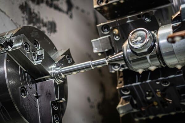
Shaft machining is usually a sequence rather than a single cutting operation. A typical route starts with rough turning to establish the centerline, continues with finish turning and feature machining, then uses heat treatment and grinding only where the final function requires them.
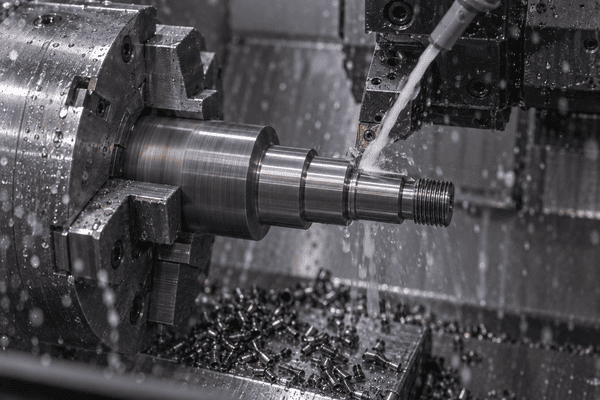
CNC turning: Produces diameters, shoulders, grooves, tapers, and external threads.
Milling or live tooling: Adds keyways, flats, cross holes, and off axis features.
Spline cutting: Transfers torque through machined or broached tooth profiles.
Heat treatment: Improves hardness and wear resistance when the design requires it.
Cylindrical grinding: Delivers controlled size and surface finish on critical bearing or seal journals.
What Controls Shaft Accuracy and Service Life?
Shaft performance is controlled by the features that mate with bearings, gears, seals, and couplings.
Diameter fit: Use the relevant ISO fit with the mating bore rather than applying an arbitrary plus or minus tolerance.
Runout and concentricity: Critical diameters should share a functional datum to prevent wobble and uneven bearing load.
Straightness: Long slender shafts can bend under cutting force, heat treatment, or clamping pressure.
Surface finish: Bearing and seal journals need a finish appropriate to the mating component, lubricant, and speed.
Shoulder geometry: Relief grooves and radii must clear the mating bearing or gear while avoiding an unnecessary stress riser.
ISO 286 provides the standard system for limits and fits, while ISO 4287 defines surface texture terminology. Tighter requirements raise cost because they may require finish passes, controlled measurement, or grinding.
When Should a Shaft Be Turned, Milled, or Ground?
CNC turning is efficient for most shaft diameters and faces. Milling or live tooling is used where torque transfer features are not rotationally symmetric. Grinding is justified after heat treatment or where the bearing seat, seal land, roundness, or surface finish exceeds what turning can reliably achieve on the actual material and length.
PCBgogo CNC machining service offers CNC turning for cylindrical features such as shafts, pins, and bushings, plus milling and mill turn machining for off axis features. Its CNC service supports DFM review, which is useful for checking center support, datum selection, and the order of heat treatment and final finishing.
PCBgogo - Precision Custom CNC Machining
Save time and reduce costs with reliable CNC milling and turning. Get precision custom parts with tight tolerances, simplified sourcing, and consistent production quality.
Get a Free Quote >
What Challenges Should Designers Plan For?
Long shafts create a tension between material removal rate and deflection. A tailstock, steady rest, staged machining, or a larger temporary support diameter can reduce vibration. Another common mistake is applying tight tolerance and low roughness to every surface, when only bearing seats and sealing lands need that level of control.
Where Is This CNC Approach Used?
Applications for shaft machining differ by load, environment, and production quantity.
Motor shafts: Motor shafts use 1045 steel, 4140 alloy steel, stainless steel, aluminum, and titanium where geometry, service load, and production volume justify CNC processing. The drawing should isolate functional dimensions so inspection effort follows the part's real job.
Gearbox input shafts: Gearbox input shafts use 1045 steel, 4140 alloy steel, stainless steel, aluminum, and titanium where geometry, service load, and production volume justify CNC processing. The drawing should isolate functional dimensions so inspection effort follows the part's real job.
Pump shafts: Pump shafts use 1045 steel, 4140 alloy steel, stainless steel, aluminum, and titanium where geometry, service load, and production volume justify CNC processing. The drawing should isolate functional dimensions so inspection effort follows the part's real job.
Transmission shafts: Transmission shafts use 1045 steel, 4140 alloy steel, stainless steel, aluminum, and titanium where geometry, service load, and production volume justify CNC processing. The drawing should isolate functional dimensions so inspection effort follows the part's real job.
Precision spindles: Precision spindles use 1045 steel, 4140 alloy steel, stainless steel, aluminum, and titanium where geometry, service load, and production volume justify CNC processing. The drawing should isolate functional dimensions so inspection effort follows the part's real job.
What Should Engineers Compare Before Choosing?
The table compares practical options associated with shaft machining.
| Option | Key characteristic | Machining or process | Typical use |
|---|---|---|---|
| Straight shaft | Uniform diameter | Turning | General drives |
| Stepped shaft | Multiple journals | Turning | Gearboxes |
| Splined shaft | Torque teeth | Turning and spline cutting | Transmissions |
| Hollow shaft | Reduced mass | Turning and boring | Motion systems |
What Drives a Manufacturable Design?
A manufacturable shaft machining specification connects function to process capability.
Functional requirement: Define what shaft machining must achieve before selecting a grade, tool, or process. Load, motion, environment, and mating components should translate into measurable drawing requirements.
Material condition: Record the incoming and final condition of 1045 steel, 4140 alloy steel, stainless steel, aluminum, and titanium. Hardness and heat treatment can change cutting behavior, distortion risk, and the operation that should create the final dimension.
Datum strategy: Build the setup around bearing journals, shoulders, threads, keyways, splines, and seal lands. Functional datums reduce accumulated error and make the inspection report easier to compare with assembly needs.
Tool access: Review reach, corner radius, chip evacuation, and holder clearance before programming CNC turning, live tool milling, heat treatment, and cylindrical grinding. Better access usually reduces setup count and avoids unnecessarily long tools.
Tolerance allocation: Apply close limits only to features that control fit, sealing, location, or motion. General surfaces can use a broader standard tolerance without weakening performance.
Workholding: Clamp against stable reference surfaces and support flexible areas near the cut. The setup must resist cutting force without temporarily bending the workpiece.
Surface finish: Specify roughness where friction, sealing, fatigue, or appearance requires it. A low Ra value on every surface increases cycle time and inspection with little functional return.
What Workflow Reduces Rework?
A reliable shaft machining workflow closes decisions in a deliberate order.
Confirm the material specification and delivery condition for 1045 steel, 4140 alloy steel, stainless steel, aluminum, and titanium.
Mark bearing journals, shoulders, threads, keyways, splines, and seal lands as critical, reference, or general features on the drawing.
Choose a setup sequence for CNC turning, live tool milling, heat treatment, and cylindrical grinding that preserves the same functional datums.
Review the main process risks, especially deflection, chatter, heat treatment movement, runout, and tolerance over specification, before approving the first article.
Define inspection records for diameter, straightness, runout, roundness, hardness, and surface finish and agree on sampling before production.
Which Quality Controls Belong in the Plan?
Quality control for shaft machining is a stack of material, process, and dimensional checks.
Incoming control: Verify material identity and condition before machining. This prevents a correct program from producing parts in the wrong alloy or hardness.
First article inspection: Measure the complete first setup before releasing the batch. The result confirms both the program and the datum transfer strategy.
In process checks: Monitor tool wear and the dimensions most sensitive to deflection, chatter, heat treatment movement, runout, and tolerance over specification. Scheduled checks are more reliable than waiting for the final inspection to reveal drift.
Final verification: Report diameter, straightness, runout, roundness, hardness, and surface finish using instruments with suitable resolution and calibration status. A quality certificate does not replace part specific evidence.
Which Challenges and Trends Matter Now?
The central challenge for shaft machining is improving precision and speed without specifying cost that the function does not need.
Higher mix production: More variants make flexible fixtures and documented setup offsets increasingly important.
Tighter functional fits: Designers are specifying closer fits while also expecting shorter lead times, which increases the value of early DFM review.
Digital inspection records: Structured measurement data helps teams connect drawing revisions, process changes, and nonconformance decisions.
FAQs
What material is best for a machined shaft?
1045 and 4140 steel are common choices for general and higher strength shafts. Stainless steel suits corrosive service, while aluminum and titanium are used where mass reduction is important.
When does a shaft need grinding?
Grinding is often used for hardened bearing seats, seal lands, or diameters with tight roundness, finish, and fit requirements. Many noncritical shaft features can be finish turned.
How do you prevent shaft deflection during machining?
Use stable workholding, support long parts with a tailstock or steady rest, control depth of cut, and sequence operations to preserve stiffness as material is removed.
An effective shaft drawing identifies the functional journals, fit class, datum, runout requirement, material condition, and finish only where needed. That lets the machinist build an accurate process without paying precision cost on nonfunctional surfaces.





