
 日本語
日本語
 한국어
한국어

CNC Deburring Guide Methods Tools and Best Practices
A practical guide to removing burrs while protecting part geometry and production consistency
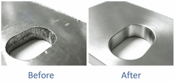
Deburring removes unwanted ridges, sharp projections, and loose fragments left after cutting. In CNC machining, a controlled deburring operation protects assembly fit, sealing surfaces, operator safety, and the finished part. It can also eliminate a separate bench operation when the machine can reach the affected edges.
The right approach depends on where the burr formed, how firmly it is attached, the specified edge condition, and the amount of variation in the part or fixture. A chamfer mill may be ideal for an accessible outside edge, while a back-chamfer tool, ball end mill, abrasive brush, or compliant holder may be needed for a hole exit or irregular contour. This guide explains how to make that choice and build a repeatable CNC deburring process without sacrificing critical dimensions.
What Is Deburring in CNC Machining
A burr forms when material bends, tears, smears, or fractures at the edge of a cut instead of separating cleanly. Common locations include the exit side of a drilled hole, the end of a milled slot, the part-off point on a turned component, and the intersection of two bores. Tool wear, unstable workholding, excessive heat, and an unfavorable tool exit can make the burr larger or less predictable.
CNC deburring uses a programmed toolpath to remove that unwanted material or create a defined edge break. Because tool position, spindle speed, feed, and engagement can be controlled, the result is usually more consistent than hand finishing. The process can run as the last operation in the same setup, which reduces handling and makes it easier to trace an edge-quality problem back to a specific tool or program revision.
Deburring and chamfering are related but not identical. Deburring removes the projection left by machining. Chamfering intentionally cuts the parent material to create a specified flat edge, often at an angle. If a drawing calls only for burr removal, an oversized chamfer can make the part nonconforming. The drawing must therefore define whether the requirement is a burr-free edge, a maximum edge break, a chamfer, or a radius.
Why Burr Control Matters
A small burr can prevent a mating component from seating, scratch a sliding surface, cut an O-ring, or detach inside a fluid passage. It may also distort an inspection result if a probe or micrometer contacts the raised material instead of the intended surface. On thin walls and miniature features, aggressive cleanup can be just as damaging as the original burr because it changes the edge or removes support from the feature.
Manual deburring adds handling and operator-to-operator variation. In-machine deburring is most valuable when the burr is stable, the tool has reliable access, and the edge requirement can be measured. Heavy, inconsistent burrs should be corrected at the machining source before automation is attempted.
Common Burr Types and What They Reveal
Rollover burrs appear when material bends over at the exit of a cut. They are common at milled edges and drilled-hole exits. A sharp cutter, supported exit edge, and suitable cutting direction can reduce their size before a deburring tool is used.
Poisson burrs result from plastic deformation and may require a cutting tool rather than a soft brush. Tear burrs have an irregular root and often point to unstable cutting or poor tool condition. Cut-off burrs remain where a part separates from stock. In practice, the burr's size and attachment matter most because a thin feather edge and a thick rolled lip need different cutting forces.
Inspect the burr at its root, not only at its visible tip. A brush may make the top look polished while leaving the attached material in place. Record the burr location, direction, approximate size, and variability across several parts. That information is the basis for choosing the tool and setting the process window.
CNC Deburring Methods and Tool Selection
| Edge or feature | Typical CNC tool | Best use |
|---|---|---|
| Accessible outside edge | Chamfer mill | Defined edge break and repeatable geometry |
| Hole entrance | Countersink or chamfer mill | Burr removal with a controlled bevel |
| Hole exit | Back-chamfer tool | Deburring without turning the part |
| Curved or undercut edge | Ball end or lollipop cutter | Contour access with programmed geometry |
| Cross-hole intersection | Cross-hole tool or flexible abrasive | Contact with the internal burr root |
| Variable surface height | Compliant holder with cutter or brush | Controlled contact across limited variation |
| Light burrs on broad surfaces | Abrasive brush | Selective finishing with low cutting pressure |
Cutting Tools for Defined Edges
Chamfer mills and countersinks remove burrs while producing a controlled bevel. They suit accessible straight edges and hole entrances where the drawing allows a defined edge break. Use the cutting portion of the tool rather than the fragile tip, and program enough clearance to avoid rubbing adjacent surfaces.
Ball end mills and lollipop cutters follow curved profiles or reach under an edge. Back-chamfer tools cut a hole exit without flipping the part. At intersecting bores, a cross-hole tool or flexible abrasive may reach the saddle-shaped edge more reliably than a rigid cutter. The tool must clear the opening without contacting the finished bore wall.
Brushes and Abrasive Tools for Light Burrs
Abrasive nylon, ceramic-fiber, or wire brushes are useful for light burrs, broad surfaces, and features with modest positional variation. Their compliance lets them follow small changes in height, but that same flexibility limits geometric precision. Brush stiffness, abrasive grade, rotation speed, feed, and contact depth all affect the result. More contact is not automatically better; excessive engagement accelerates wear, generates heat, and can round an edge beyond the requirement.
Grinding points and abrasive wheels remove harder burrs but require careful control near finished surfaces. If prolonged grinding is necessary, review the upstream operation first.
Compliant Holders for Part Variation
A rigid tool follows a position in the CNC coordinate system. If a casting, welded part, or flexible fixture shifts relative to that position, the edge break will change. A compliant or floating holder allows limited movement while maintaining contact with the edge. This can improve consistency on parts with expected variation, provided the compliance range, contact force, and tool orientation suit the feature. Compliance cannot correct poor fixturing or large location errors; it only manages variation inside a validated window.
How to Protect Tolerances During Deburring
Start with the drawing. Identify datum surfaces, sealing lands, bearing fits, thread starts, thin walls, and any edge with a specified chamfer or radius. Mark these as controlled features in the CAM plan. A general note such as break sharp edges leaves room for interpretation, so critical edges should have a measurable limit agreed before production.
Use light, repeatable engagement and remove only enough material to satisfy the edge requirement. Establish the first process on a representative part, then measure the feature before and after deburring. For a cutting tool, adjust the path or wear offset in small steps. For a brush, feed and contact depth usually have a strong influence on edge break, while spindle speed changes cutting frequency and heat. Change one variable at a time so the effect is clear.
Keep the tool away from inspection surfaces. At a hole edge, cut the burr root without dragging along the finished diameter. Support thin walls and inspect both the edge and adjacent dimension when a tight tolerance is nearby.

A Practical CNC Deburring Workflow
Define the finished edge. Translate the drawing into a measurable condition. State which edges must be burr-free, which receive a chamfer or radius, and which surfaces must remain untouched.
Reduce the burr at the source. Confirm the primary cutting tool is sharp, the part is supported, and chips leave the cut. Review operation order and tool exit direction. A small, consistent burr is easier to remove than a changing one.
Map access and collision risks. Check the tool body, holder, spindle nose, clamps, and neighboring walls. Simulate multi-axis motion and verify safe approach and retract moves.
Match the tool to the burr. Use a rigid cutter for a defined edge, a back-deburring tool for a hole exit, a contouring tool for a three-dimensional edge, or a compliant abrasive tool for light burrs and controlled variation.
Build a conservative toolpath. Begin with light engagement and a stable feed. Avoid dwelling at corners because it can enlarge the edge break. Maintain a smooth tool orientation on three-dimensional contours.
Approve the first part. Inspect every targeted edge under suitable lighting and magnification. Measure specified chamfers or radii and confirm that adjacent dimensions, finishes, and threads remain acceptable.
Control wear in production. Define a tool-life check or an edge-quality sampling interval. A worn brush becomes smaller and less aggressive; a dull cutter may push material and create a secondary burr. Use offsets only within the approved process window.
Deburring Different CNC Materials
Aluminum often produces soft, attached burrs that can smear or fold. Sharp cutting edges, effective chip evacuation, and limited heat help prevent material from welding back onto the edge. A clean cutting pass is usually preferable to heavy brushing when a precise chamfer is required.
Carbon and alloy steels can produce harder burrs whose behavior changes with hardness and cutting condition. Rigid carbide tools work well for defined edges, while abrasive tools can finish light residual burrs. Stainless steel is tougher and prone to work hardening when a tool rubs. Keep the tool cutting, avoid unnecessary dwell, and replace worn tools before edge quality drifts.
Machined plastics may bend, melt, or leave a fuzzy edge. Use sharp tools, low pressure, and limited heat. Brittle plastics can chip or crack, while fiber-reinforced materials also require dust control and inspection for delamination.
Inspection and Process Control
A part is not adequately deburred merely because it feels smooth. Visual inspection should use consistent lighting and magnification appropriate to the feature. A swab or soft probe can reveal a loose projection in an accessible area, but it does not measure edge geometry. Use an optical comparator, microscope, edge gauge, or another validated method when the chamfer or radius has a numerical requirement. Critical internal passages may require a borescope or a sectioned sample during process development.
Link incoming burr condition, deburring tool life, and final acceptance in the control plan. Record the proven tool, holder, program revision, offsets, feed, and inspection method. Increase sampling after a primary cutting-tool change because the incoming burr may also change.
Common CNC Deburring Problems
Burr remains. The tool may be passing above the burr root, the brush may be worn, or the primary operation may be creating a heavier burr. Verify access and incoming condition before increasing engagement.
Edge break is uneven. Check runout, part location, workholding, tool deflection, and whether a rigid tool is being used on a variable surface. A compliant holder may help only after the fixture is stable.
A secondary burr appears. A dull cutter, rubbing toolpath, or unsuitable cutting direction can roll material onto the opposite side. Restore a clean cutting action and review entry and exit moves.
Chamfer is too large. Reduce engagement or change the path offset. Confirm that tool diameter and included angle match the CAM definition, and measure the edge instead of judging it by eye.
Surface is scratched or overheated. Check abrasive contact, trapped chips, coolant or air delivery, spindle speed, and dwell. Protect finished surfaces and shorten contact time.
Tool life is inconsistent. Track the burr entering the process. Variation often originates in the drilling, milling, or turning tool rather than in the deburring tool itself.
When In Machine Deburring Is Not the Best Choice
CNC deburring works best when the edge is reachable and the result is local and measurable. Thermal, electrochemical, abrasive-flow, vibratory, or robotic processes may be better for inaccessible passages, widespread heavy burrs, or uniform cosmetic finishing. Compare selectivity, dimensional risk, cleanliness, cycle time, volume, and extra handling.
Frequently Asked Questions
What is the best CNC deburring tool
There is no universal tool. Match a chamfer mill, back-chamfer tool, contour cutter, or compliant abrasive tool to the burr root, access, material, and specified edge condition.
Can deburring change CNC part tolerances
Yes. Deburring can enlarge a chamfer or affect a nearby surface. Protect tolerances with light engagement, controlled toolpaths, first-part measurement, and a defined wear limit.
How can burrs be reduced before deburring
Keep cutting tools sharp, stabilize the workpiece, support the tool exit, control chips and heat, and review cutting direction. A smaller incoming burr makes finishing more predictable.
Build Deburring Into the Machining Plan
Reliable deburring starts with a defined edge and a stable incoming burr. Select a tool that reaches the burr root, validate the result against the drawing, and control tool life. The result is a documented CNC operation rather than variable rework.





