
 日本語
日本語
 한국어
한국어

Aluminum Milling Guide for CNC Machining
A practical guide to alloys, cutting tools, speeds and feeds, chip control, and surface finish
Aluminum milling can remove material quickly and produce accurate parts, but the process is less forgiving than the metal's softness suggests. Aluminum forms large chips and can adhere to an edge when the tool rubs or recuts material. Reliable results require the alloy, cutter, chip load, toolpath, workholding, and coolant to work together.
This CNC guide provides conservative starting points for 6061 aluminum and a practical tuning method. They are not universal recipes. The tool manufacturer's data takes priority, and every setup must be proven with the actual spindle, holder, fixture, and toolpath.
Why Aluminum Milling Behaves Differently
Aluminum permits higher cutting speeds than steel but introduces another failure mechanism. Ductile material can smear onto the rake face and form a built-up edge. The buildup changes tool geometry, raises cutting force, marks the wall, and may break the cutter. Heat worsens adhesion, although rubbing or trapped chips often creates the heat.
A healthy cut produces distinct chips that carry heat away. Dust, flakes, smeared chips, or long strands left in a pocket signal trouble. Simply reducing feed may make it worse: when feed per tooth is too small, the edge rubs instead of shearing a chip.
Choose the Aluminum Alloy for the Part
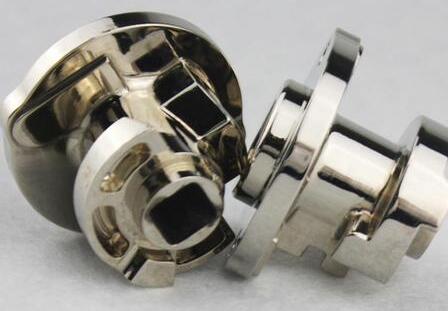
Alloy and temper affect chip shape, cutting force, distortion, corrosion behavior, and finish. Confirm the material certificate or stock designation before developing the process. Similar-looking pieces can cut differently when one is soft sheet and the other is heat-treated plate.
| Alloy | Machining behavior | Typical CNC uses | Planning note |
|---|---|---|---|
| 6061 T6 | Good machinability and predictable chips | Housings, brackets, fixtures, prototypes | A sound default when strength and general performance matter |
| 7075 T6 | Machines cleanly but has higher strength | Highly loaded structures, tooling, aerospace parts | Use when strength justifies higher material cost |
| 2024 T3 | Good machinability with useful fatigue strength | Aircraft structures and precision components | Protect against corrosion when the environment requires it |
| 5083 | Moderate machinability and more ductile behavior | Marine and welded structures | Plan carefully for chip control and distortion |
| 5052 | Soft and prone to gummy chips | Formed sheet components and corrosion resistant parts | Sharp tools and strong lubrication become more important |
Temper matters as much as alloy number. Heat-treated T6 stock is generally more stable to cut than a soft condition. Large pockets and thin sections may move as internal stress is released. Balanced roughing, a uniform finish allowance, and a pause before finishing can limit this movement.
Select an End Mill That Makes Room for Chips
Use a sharp carbide end mill designed for nonferrous materials. Aluminum cutters typically combine a positive rake, polished flutes, generous flute valleys, and a higher helix angle. These features reduce cutting force and help large chips leave the cut.
One or two flutes provide maximum chip space and are useful on high-speed routers, small machines, and full-width slots.
Three flutes can raise productivity and give stable finishing performance when the machine and evacuation system can support the higher feed rate.
A 35 to 40 degree helix is a practical choice for roughing and slotting. A 45 degree helix can improve finishing and low-radial-engagement toolpaths, although its stronger axial pull requires secure workholding.
Polished uncoated carbide is a dependable baseline. Coatings intended for aluminum, such as ZrN or TiB2, can reduce adhesion. Avoid assuming that a coating designed for ferrous materials will also suit aluminum.
Keep tool stickout as short as the feature allows. Excess reach can cause chatter and tapered walls even at a reasonable chip load. Check the collet, holder, and edge for runout or damage before changing the program.

Calculate Speeds and Feeds from Chip Load
Start with the cutter supplier's cutting speed and feed per tooth for the exact tool. Convert cutting speed to spindle speed, then calculate feed rate. In metric units:
Spindle speed in rpm = cutting speed in m per min x 1000 divided by pi x tool diameter in mm
Feed rate in mm per min = spindle speed x number of flutes x feed per tooth in mm
A 10 mm three-flute carbide end mill at 300 m/min gives about 9,550 rpm. At 0.08 mm per tooth, feed is about 2,290 mm/min. The calculation does not prove the machine can hold the cut. Power, stickout, engagement, fixture stiffness, and entry strategy still set the operating window.
Conservative Starting Window for 6061 T6
| Operation | Cutting speed | Feed per tooth | Radial engagement | Axial depth | Conditions |
|---|---|---|---|---|---|
| Side roughing | 200 to 400 m/min | 0.04 to 0.10 mm | 10 to 25 percent D | Up to 1 to 2 D | Rigid setup, sharp 2 or 3 flute carbide, effective evacuation |
| Full slot | 150 to 300 m/min | 0.03 to 0.07 mm | 100 percent D | Start at 0.25 to 0.5 D | Use two flutes, modest entry, and continuous chip clearing |
| Wall finishing | 250 to 500 m/min | 0.02 to 0.06 mm | 2 to 8 percent D | Use available flute length | Leave a uniform allowance and use one continuous pass |
| Floor finishing | 250 to 500 m/min | 0.02 to 0.06 mm | 5 to 20 percent D | 0.1 to 0.5 mm | Control runout and use consistent stepover |
The ranges are broad because tool diameter changes practical chip load, and machines differ in stiffness and torque. Start low when the cutter is small, stickout is long, the workpiece is thin, or the machine is light. If rpm is capped, recalculate feed from actual spindle speed to preserve chip load.
Use Toolpaths That Keep Cutter Load Predictable
Climb milling is usually preferred on a backlash-free CNC machine because the chip starts thick and thins toward the exit. This reduces rubbing and directs chips behind the cut. Use conventional milling only when the finishing or workholding strategy supports it.
Enter pockets with a ramp or helix unless the cutter is designed to plunge. Adaptive roughing keeps radial engagement low and the engagement angle consistent, allowing deeper axial cuts with manageable load. Round sharp toolpath corners or reduce feed there to prevent a sudden engagement spike.
Treat full-width slotting as a separate process. Both sides of the cutter engage and chips have little room to escape. Use fewer flutes, reduce axial depth and feed from the side-milling setup, and direct air or coolant into the slot.
Control Chips Heat and Lubrication
Chip evacuation is central to stable aluminum milling. Flood coolant cools, lubricates, and transports chips on an enclosed machining center. Minimum quantity lubrication adds lubricity with less fluid, while directed air can clear chips on suitable routers. Delivery must reach the cutting zone without creating unsafe mist or flying chips.
Dry milling can work in an open side cut with strong air evacuation, but deep pockets and slots are less tolerant. Follow the fluid supplier's concentration, compatibility, ventilation, and fire-safety instructions. Never improvise with flammable liquid in an enclosed or poorly ventilated machine.
Clean, separate chips suggest that each edge is shearing material. Smeared chips or packed flutes point to weak lubrication, poor evacuation, a dull edge, runout, or too little chip load. Stop before buildup damages the part or tool.
Improve Accuracy and Surface Finish
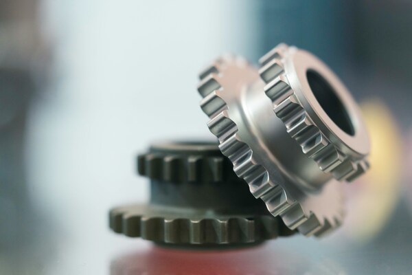
Surface finish depends on the whole setup. A new cutter cannot compensate for a flexible fixture, and a slower feed cannot correct spindle runout. Clamp near the cut, support thin floors, minimize overhang, and avoid distorting the part.
Rough with a consistent allowance, then use a separate finishing pass with stable engagement. A light radial wall pass using the usable flute length can reduce witness lines. On floors, use a repeatable stepover and keep chips from being dragged under the cutter. Check deflection before changing wear compensation.
For thin walls, leave support material while nearby features are roughed, alternate sides when possible, and use light finishing passes. Inspect after unclamping because residual stress and clamp force can hide movement in the fixture.
Troubleshoot Aluminum Milling by Symptom
| Symptom | Likely causes | First checks and corrections |
|---|---|---|
| Aluminum welded to the edge | Chip recutting, rubbing, weak lubrication, dull or unsuitable tool | Clear the cut, inspect the edge, restore chip load, improve delivery, and use aluminum geometry |
| Chatter marks | Long stickout, weak workholding, runout, unstable engagement | Shorten the setup, support the part, verify holder condition, and change engagement or rpm |
| Rough or torn wall | Built-up edge, deflection, interrupted finishing pass | Use a clean sharp tool, leave uniform stock, and finish in one stable pass |
| Tool breaks in a slot | Packed chips, excessive depth, poor entry, feed mismatch | Use fewer flutes, reduce depth, ramp in, improve evacuation, and recalculate feed |
| Oversize or tapered feature | Tool deflection, runout, thermal drift, part movement | Measure runout, reduce stickout and load, verify fixture, then adjust compensation |
| Burrs on the exit edge | Dull edge, unsupported material, unfavorable exit direction | Replace or inspect the tool, support thin edges, and revise the final toolpath direction |
Change one variable at a time and record alloy, tool, runout, stickout, rpm, feed, engagement, coolant, spindle load, chip appearance, tool life, and inspection results. The record turns one successful cut into a repeatable aluminum milling process.
A Reliable Setup Sequence
Confirm the alloy, temper, stock condition, drawing tolerances, and areas most likely to distort.
Choose an aluminum-specific cutter with enough flute space and minimum practical reach.
Use supplier data to calculate rpm and feed, then reduce engagement for a cautious first cut.
Plan ramped entry, climb milling, corner control, and an evacuation path for every pocket or slot.
Prove the cut while watching chips, sound, spindle load, workholding, and coolant delivery.
Measure the rough feature, leave uniform stock, finish, and inspect again after unclamping.
Frequently Asked Questions
What is the best aluminum for CNC milling
6061-T6 is a versatile choice for general CNC parts because it combines good machinability, useful strength, corrosion resistance, availability, and cost. Choose 7075-T6 for higher strength, 2024 for specific fatigue requirements, and 5xxx alloys when corrosion performance or welding drives the design.
What is the best end mill for aluminum
Choose a sharp, polished carbide end mill with aluminum geometry. Two flutes suit slots and chip-limited machines; three can improve productivity and finishing when evacuation is strong. Match diameter, flute length, helix, and coating to the operation.
Can aluminum be milled without coolant
Yes. Open cuts can run dry with a suitable tool and continuous air evacuation. Deep slots, pockets, gummy alloys, and production work usually benefit from controlled lubrication or coolant. Remove chips before the cutter meets them again.
Why does aluminum stick to the cutting tool
Pressure, friction, and trapped heat promote built-up edge. Common triggers include a dull or unsuitable tool, insufficient chip load, poor evacuation, runout, and weak lubrication. Inspect the edge and chips before changing parameters.
How should aluminum milling parameters be optimized
Begin with tool-specific data, calculate rpm and feed, and choose conservative engagement for the machine. Observe chips and spindle load, change one factor at a time, measure the part, and document the combination that meets finish, tolerance, tool-life, and cycle-time targets.
Final Takeaway
Successful aluminum milling requires a sharp tool, a real chip load, reliable chip evacuation, and a rigid setup. Once these conditions are stable, increase productivity through controlled tests. Treat the first parameter set as a hypothesis, read the chips, measure the part, and build the final CNC process from machine evidence.





