
Manufacturing an instrument - have a couple of questions
I have pretty much finished the circuitry and programming for a new project and I'm now at the case design stage. And I have never designed a case before.
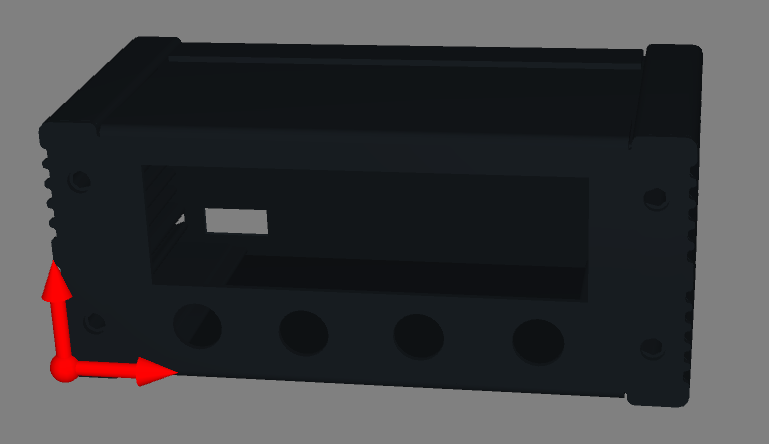
The case design is simple - just an aluminium extrusion with the switches, connectors etc. on the front and back panels. A picture of it is below.
My questions are;
1. The large cutout at the front is for a 16x2 lcd display. What is the best way to attach the display behind and to the front panel? I assume it will require standoffs but I don't want to be able to see the connectors on the front. Is there another way?
2. The small hole in the back panel is to simply hold a 3 terminal screw terminal. Can someone steer me in the right direction to find something that will give me the screw terminals on the outside and some kind of pcb to pcb connector on the inside, or just 3 pins that I can solder to?
Thanks.


- Comments(1)
A****min
Jun 15.2019, 09:05:47
I take it the round holes underneath the LCD cut-out are for buttons. So you could mount the LCD on the same board your button are on using a few stand-offs.
In that case I'd make the cut-out for the LCD the same size or very slightly smaller than the actual size of the visible LCD screen. That way you would not see the bezel or the "innards" of the display.
If I interpret your picture correctly the front and the top and bottom side panels are one bent piece of sheet metal. In that case I'd mount all the PCB's inside as a sandwiched stack on the back panel.

