
Advice for Mains AC PCB
Hi I'm making a step down converter PCB in orcad allegro, that will be directly connected to mains AC. My main doubt is what connector pcb footprint could I use for that.
Specs are:
Input
Mains AC: 220V RMS, 50Hz
Load: Something around 500W
Out
FS=10Khz
full DC range
4A Maximum DC current
It's just experimental so, no protections will be used. Currently I put on the output and mains connector a TO-220 Footprint. I know it's undoubtedly insufficient.
My current schematic is this
![]()
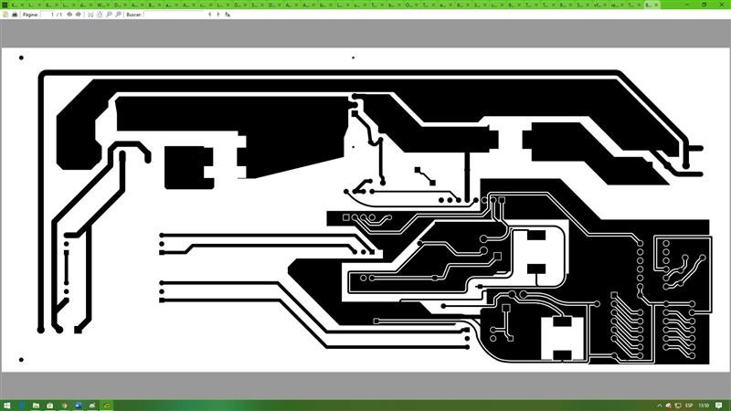
I've made an artwork, with controller aux source included. What you think about AC or DC power Traces? (upper side, left side)

- Comments(1)
A****min
Aug 31.2019, 12:12:59
Please put 1M resistors in parallel with C10 and C11. It is not wise to let those caps charged after you unplug everything and touch the board.

