
What Is a PCB Fuse? Types, Selection, and Fuse Holder Guide
KEY DEFINITION A PCB fuse is a circuit protection component designed to interrupt the current path when the current exceeds a predefined threshold, helping prevent damage to the PCB and downstream electronic components. Common fuse types include surface mount (SMD) fuses, through-hole cartridge fuses, and resettable PTC fuses. Selection is typically based on key electrical parameters such as current rating, voltage rating, and response speed to ensure proper protection in different circuit applications.
Picture a power surge hitting a circuit board with nowhere for the excess current to go. Without a fuse in the path, that surge can cook a trace, melt a connector, or take out an entire IC in a fraction of a second.
This guide walks through the main PCB fuse types, how fuse holders and trace fuses fit into the picture, and the selection and layout rules that keep a board protected without nuisance tripping.
What Is a PCB Fuse?
A PCB fuse is a sacrificial component, soldered or clipped onto a circuit board, that opens the current path once current exceeds its rated threshold for a defined period. It sits in series with the circuit it protects, usually right after the power input. Inside, a calibrated conductor heats up under overcurrent until it melts, creating a permanent open circuit. Fuses are rated in amps for current and volts for the maximum voltage they can safely interrupt, and most consumer electronics fuses fall in the 0.1A to 30A range.
Types of PCB Fuses
PCB fuses come in several form factors, each suited to different board layouts and current levels.
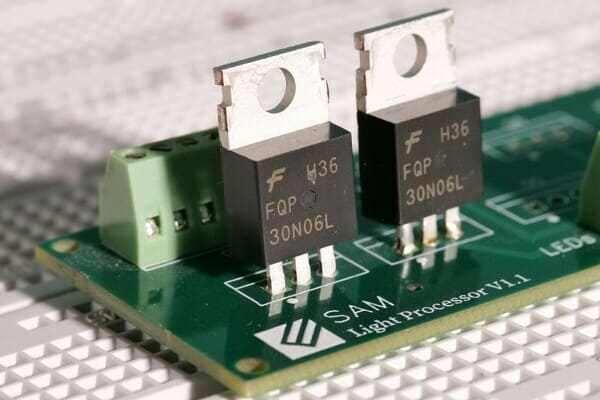
SMD Fuses: Small rectangular chip fuses that reflow solder directly onto pads, similar to a resistor footprint. They save board space and are common in compact consumer devices, typically rated up to 10A.
Through-Hole Cartridge Fuses: Cylindrical glass or ceramic fuses (commonly 5x20mm or 6.3x32mm) that mount in a holder or clip, making them easy to inspect and swap without desoldering.
Resettable PTC Fuses: Polymeric positive temperature coefficient devices that increase resistance under overcurrent instead of breaking permanently, then reset once the fault clears and the device cools.
Radial and Axial Lead Fuses: Leaded fuses soldered directly into the board, radial with both leads on one side and axial with leads on opposite ends, used where a holder is not needed.
Fast-Blow vs Slow-Blow Fuses: Fast-blow fuses open almost immediately at rated current for sensitive electronics, while slow-blow (time-delay) fuses tolerate brief inrush spikes common in motors and transformers before opening.
PCB Trace Fuses: Using Copper Traces as a Fuse
A PCB trace fuse is a section of copper trace deliberately narrowed so it melts and opens the circuit before current reaches a damaging level elsewhere on the board. The behavior follows Onderdonk's equation, which relates trace cross-sectional area, melting temperature, and time to the current that will fuse the copper. Because a trace heats up well before it actually melts, designers typically target only 20% to 30% of the calculated fusing current, leaving margin so nearby components are not damaged by the heat buildup.
Trace fuses are inexpensive since they add no extra part, but they are not well suited to applications that need a reliable, repeatable trip point. Trace width, copper thickness, soldermask coverage, and even board-to-board manufacturing variation all shift the actual blow current, so most designs reserve trace fuses for non-critical, low-cost protection and use a dedicated SMD or through-hole fuse wherever certified, repeatable protection is required.
PCB Fuse Holders: Mounting Types and Selection
A PCB fuse holder is a mechanical socket mounted on the board that lets a cartridge fuse be inserted, removed, and replaced without soldering. Holders matter most in field-serviceable equipment, where a blown fuse needs to be swapped quickly.
Through-Hole Fuse Clips: Two-piece spring clips soldered to through-hole pads that grip a cylindrical cartridge fuse, the most common style for 5x20mm and 6.3x32mm fuses.
SMD Fuse Sockets: Reflow-soldered holders for the same cartridge fuse sizes, used when the assembly line is fully surface mount and through-hole processing should be avoided.
Panel Mount Holders: Holders that pass through an enclosure wall so a user can access and replace the fuse from outside the box, common in industrial power supplies.
Sizing a holder starts with the cartridge fuse dimensions it needs to accept, most commonly 5x20mm for general electronics, 6.3x32mm for higher current applications, and 10x38mm for higher voltage industrial or solar circuits. A soldered fuse works fine for protection that should never need field access, while a holder is worth the extra board space whenever a technician or end user should be able to replace the fuse without opening a soldering iron.
Key Factors in Choosing the Right PCB Fuse
Choosing the right fuse comes down to a handful of electrical and environmental factors that all need to line up.
Current Rating: Rate the fuse above normal operating current with margin for tolerance and derating. For a circuit that draws 1.6A continuously, a common approach is to select a fuse rated around 2A, giving roughly 25% headroom above the steady operating load.
Voltage Rating: The fuse voltage rating must meet or exceed the circuit's maximum voltage, since a fuse rated below the applied voltage may arc internally instead of clearing the fault.
Breaking Capacity: This is the maximum fault current the fuse can safely interrupt without rupturing; industrial and mains-connected circuits often need breaking capacities well above what the fuse's normal current rating alone would suggest.
Response Time: Fast-acting fuses suit sensitive semiconductor circuits, while slow-blow fuses are better matched to motors, transformers, and other loads with a predictable inrush current.
Environmental Derating: Fuse current ratings drop as ambient temperature rises, and datasheet derating curves commonly apply a factor around 0.8 at 50 degrees Celsius, so boards operating in enclosed or high-temperature environments need a higher-rated fuse to hold the same effective protection level.
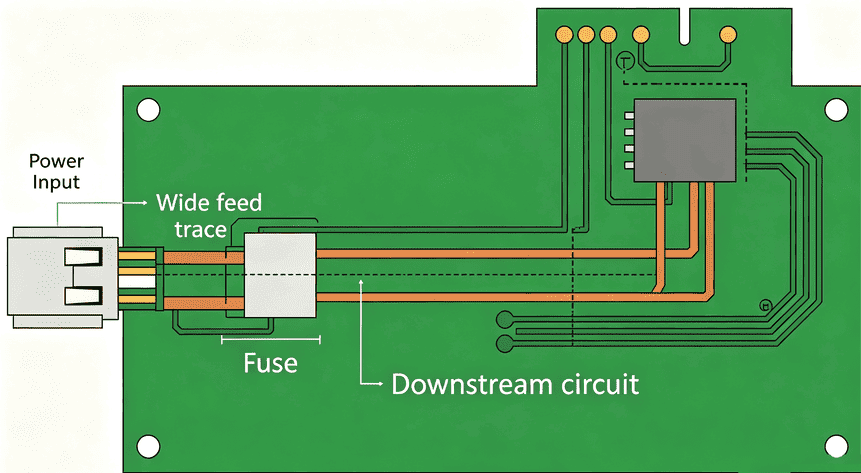
PCB Fuse Placement and Layout Best Practices
Good fuse performance depends as much on the surrounding layout as on the fuse itself. Traces feeding into and out of the fuse must be sized to carry the full rated current without excessive heating, following the conductor width guidance in IPC-2221 and the current-carrying capacity data in IPC-2152. Place the fuse as close as possible to the power entry point, immediately after the input connector or battery terminal, so it protects the maximum amount of downstream circuitry.
Keep the fuse away from heat-generating components and add thermal relief on its pads so it is not pre-heated by adjacent parts, which can cause nuisance tripping. Label the fuse rating clearly on the silkscreen, for example "F1 2A 250V," so it is identifiable during assembly, inspection, or field service.
Getting a board this far, from a validated fuse placement to a manufacturable trace layout, depends heavily on how the fabricator handles copper thickness and hole tolerances during production. PCBgogo's fabrication process holds tight control over trace width and plating consistency, which matters directly for how predictably a fuse and its feed traces perform once the board is built and in service. Please feel free to contact us to discuss your project requirements and receive customized manufacturing support and optimization advice from our PCB experts.
Testing PCB Fuses
Confirming a fuse is intact, or diagnosing a blown one, only takes a few basic checks:
1. Start with a visual inspection, since many blown glass cartridge fuses show a visibly broken or discolored element.
2. Follow with a continuity test using a multimeter set to resistance or continuity mode, checking for a near-zero reading across the fuse with power removed from the board.
3. A functional test, applying rated load and confirming the circuit powers correctly, confirms the fuse and its connections are both sound.
Conclusion
Selecting the right PCB fuse means matching current rating, voltage rating, and response time to the circuit, then backing that choice up with correct trace sizing and placement on the board. For your next design, work with a fabricator that can hold consistent copper and hole tolerances so the protection you designed on paper performs the same way on the finished board.
Frequently Asked Questions
What is the difference between a PCB fuse and a circuit breaker?
A PCB fuse is a one-time device that must be physically replaced after it opens, while a circuit breaker can be manually or automatically reset after tripping. Fuses are generally smaller, cheaper, and faster acting, which is why they dominate compact electronics, while breakers are more common in equipment where frequent resets are expected.
What size fuse holder do I need for a 5x20mm fuse?
Match the holder to the fuse's physical dimensions first, then confirm its current and voltage rating meets the circuit's requirements. 5x20mm holders are the most widely stocked size and fit the majority of general-purpose glass and ceramic cartridge fuses used in consumer and industrial electronics.
Can a PCB trace be used as a fuse?
Yes, a narrowed copper trace can act as a fuse by melting open under overcurrent, but the blow current varies with manufacturing tolerances, soldermask coverage, and ambient temperature. This makes trace fuses suitable for low-cost, non-critical protection rather than applications needing a certified, repeatable trip point.
How do I know if a PCB fuse is blown?
Check for a visible break or discoloration in the fuse element, then confirm with a multimeter continuity test across the fuse leads with the board powered off. A reading of infinite resistance, or no continuity, confirms the fuse has opened.
What is the typical current rating margin for a PCB fuse?
A common practice is rating the fuse around 20% to 25% above the circuit's normal operating current, which avoids nuisance tripping from minor load variation while still clearing genuine fault conditions promptly.


