
 日本語
日本語
 한국어
한국어

What Is a Cold Solder Joint? A Complete Guide for Reliable Repair Work
A cold solder joint is one of the most common and consequential defects in electronics manufacturing. Despite being small in scale, it can silently undermine the reliability of an entire printed circuit board (PCB), causing intermittent failures, increased electrical resistance, or complete circuit breakdown. Understanding what a cold solder joint is, how to spot one, and how to prevent it is essential knowledge for engineers, technicians, and hobbyists alike.
What Is a Cold Solder Joint?
A cold solder joint forms when solder does not melt fully or fails to flow and bond correctly to the component lead and PCB pad during the soldering process. Instead of the solder becoming completely liquid and spreading evenly, it remains partially solid or cools too rapidly, producing a joint that is mechanically weak and electrically unreliable.
Visually, a properly formed solder joint appears shiny, smooth, and slightly concave, forming a neat fillet around the component lead. A cold joint, by contrast, looks dull, grainy, or lumpy. It may appear frosted or crystalline rather than reflective. For through-hole components, the ideal joint should have a shiny, cone-shaped profile with the solder sloped at roughly 40 to 70 degrees between the pad surface and the pin. When that shape is absent or the surface texture looks rough, a cold joint is likely the culprit.
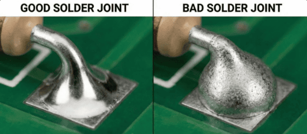
Cold joint solder problems are not just cosmetic. Because the solder has not fully bonded to the metal surfaces, the joint may exhibit higher electrical resistance than normal, causing components to behave erratically or fail entirely under load. Mechanical stress from vibration, thermal cycling, or even handling can cause a cold joint to crack and open the circuit.
Common Causes of Cold Solder Joints
Understanding what triggers cold solder joints is the first step toward eliminating them. The most frequent causes include:
Insufficient heat: The soldering iron must reach and maintain an adequate temperature to melt the solder alloy fully and heat both the component lead and the PCB pad simultaneously. If the iron temperature is set too low, or the iron is not held in contact long enough, the solder will not flow into a proper bond. For most standard solder alloys, the iron tip should be approximately 15°C above the solder's melting point, and contact should be maintained for at least a few seconds after the solder flows.
Movement during cooling: If the component or the board is disturbed while the solder is still transitioning from liquid to solid, the joint becomes a “disturbed joint.” The result is an irregular, grainy surface that may look acceptable but has poor structural and electrical integrity.
Surface contamination: Oils, oxidation, flux residue, or other contaminants on pads or component leads prevent solder from wetting properly. Solder requires clean metal surfaces to form the intermetallic bond that makes a joint strong. Contamination causes the solder to bead up or fail to spread, leaving behind a weak, cold-looking connection.
Inadequate solder quantity: Too little solder leaves the joint with insufficient metal to form a complete fillet. This results in a weak mechanical connection and poor electrical conductivity.
Old or degraded solder paste: In automated PCB assembly using reflow soldering, expired or improperly stored solder paste loses its flux activity. Without effective flux, the solder cannot clean the surfaces during reflow, significantly increasing the likelihood of cold joints across an entire production batch.
How to Identify Cold Solder Joints
Catching cold solder joints early saves time and prevents field failures. There are several reliable inspection methods:
Visual inspection: Under good lighting or a magnifying loupe, look for dull, grainy, or uneven surfaces. A healthy joint is shiny and smooth. Any joint that looks frosted, lumpy, or irregular warrants closer attention.
Multimeter testing: Measuring continuity or resistance across a suspected joint can reveal hidden problems. A joint that intermittently opens or shows abnormally high resistance is a classic sign of a cold solder connection.
Automated optical inspection (AOI): In professional PCB manufacturing environments, AOI systems use cameras and software to scan boards at high speed, flagging solder joints that deviate from expected shape, size, or reflectivity.
X-ray inspection: For BGA packages and other components where joints are hidden beneath the device body, X-ray imaging is the only reliable way to inspect solder connections without desoldering.
How to Fix a Cold Solder Joint
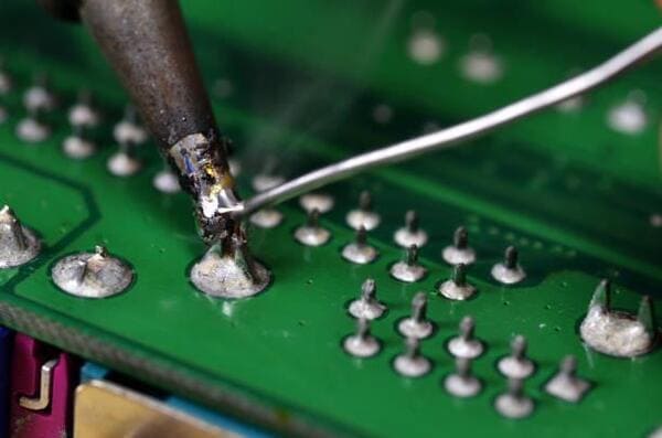
Fixing a cold solder joint is generally straightforward when caught early. The process involves reheating the joint until the existing solder flows completely, and then either allowing it to solidify undisturbed or adding a small amount of fresh solder to ensure complete coverage. In many cases, simply touching the iron to the joint and letting the solder re-melt and reflow is enough to restore a solid connection.
For more severe cases where the joint is badly oxidized or contaminated, it is better to remove the old solder entirely using a solder sucker or desoldering wick, clean the pad and lead thoroughly, and re-solder from scratch. Applying fresh flux before re-soldering helps the solder wet the surfaces properly and produces a more reliable result.
Preventing Cold Solder Joints: Best Practices
Prevention is far more efficient than rework. Following these practices during manual and automated soldering will significantly reduce the occurrence of cold joints:
Calibrate and maintain soldering equipment: Use a temperature-controlled soldering station and verify tip temperature regularly. A worn or oxidized tip transfers heat poorly; replace tips as needed.
Clean and tin the iron tip: A clean, tinned tip ensures maximum heat transfer to the joint. Wipe the tip frequently on a damp sponge or brass wool during use.
Heat both surfaces simultaneously: The iron should contact both the pad and the component lead at the same time. Apply solder to the joint, not the iron, so the solder is drawn in by the heated surfaces.
Allow joints to cool undisturbed: After removing the iron, hold the component still for several seconds while the solder solidifies. Even slight movement during this period can create a disturbed joint.
Use quality materials: High-grade solder wire with appropriate flux core, stored correctly, makes a significant difference in joint quality. For reflow processes, use solder paste within its shelf life and store it under proper refrigeration.
Start with high-quality PCBs: The surface finish and pad quality of the PCB itself play an important role in soldering success. PCBs with well-finished pads and consistent surface coatings accept solder more reliably. Manufacturers like
PCBgogo are known for their stringent quality control and consistent surface finishes, which give assemblers a strong foundation for defect-free soldering. Starting with a high-quality board reduces the variables that can lead to cold joints during assembly.
Cold Solder Joints in Automated Assembly
While much of the discussion around cold solder joints focuses on hand soldering, they are equally prevalent in automated assembly environments. In reflow soldering—the dominant method for surface-mount components—cold joints typically result from an incorrect temperature profile, inadequate preheat, insufficient peak temperature, or poor solder paste quality. If the board does not reach the required peak temperature uniformly, certain areas may produce cold joints even while others appear perfect.
Wave soldering, used for through-hole components, can produce cold joints if the wave temperature is too low, the conveyor speed is too fast, or the flux is insufficiently active. Regular profiling of reflow ovens and wave machines, combined with rigorous incoming inspection of solder materials, is essential for maintaining consistently high first-pass yields in production.
Conclusion
Cold solder joints remain one of the most prevalent and preventable defects in PCB assembly. Whether you are working on a hobby project at the bench or overseeing a high-volume production line, understanding the causes, visual signs, and corrective actions for cold joints is foundational knowledge. Proper technique, well-maintained equipment, quality solder materials, and reliable PCBs are the four pillars of consistent, defect-free soldering.
For projects where board quality cannot be left to chance, working with a reputable PCB manufacturer makes a real difference. PCBgogo (pcbgogo.com) offers professional-grade PCBs backed by strict quality control processes—giving engineers and assemblers confidence that the board itself will not be a source of soldering problems. If you are planning a new project and want to minimize rework and field failures from the ground up, requesting a quote from a trusted manufacturer is a smart first step.
FAQ
1. What does a cold solder joint look like?
It usually appears dull, grainy, or frosted instead of shiny and smooth. Good joints are bright and slightly concave.
2. What causes cold solder joints most often?
The main causes are insufficient heat, movement while cooling, contaminated surfaces, and poor-quality or insufficient solder.
3. Can a cold solder joint still work temporarily?
Yes, but it’s unreliable. It may pass initial testing but fail later due to vibration, heat changes, or load stress.
4. How do you quickly fix a cold solder joint?
Reheat the joint until the solder fully melts and flows properly. If needed, add a small amount of fresh solder and flux.
5. How can I prevent cold solder joints in future projects?
Use proper soldering temperature, clean surfaces, stable components during cooling, and high-quality PCB boards and solder materials.





