日本語
 한국어

What Is a USB Pinout? A Complete Guide to USB Types
Quick Answer A USB pinout maps each connector contact to power, ground, data, configuration, or sideband functions. For PCB design, the useful USB pinout is not just a pin list: it must match the connector view, protocol speed, power role, cable wiring, protection parts, and the exact footprint used on the board.
Key Takeaways
Connector shape and protocol are different. A USB-C connector may carry only USB 2.0, or it may support USB 3.2, USB4, alternate modes, and USB Power Delivery.
Count functions, not only contacts. A USB 2.0 Type-A USB pinout has four contacts; USB 3.x Type-A adds five SuperSpeed contacts; a full USB Type-C receptacle has 24 contacts.
Use the component drawing as the final authority. Plug and receptacle views are mirrored easily, and PCB footprint numbering may be shown from the mating face or board side.
Route for the implemented speed. Keep differential pairs over a continuous reference plane, control nominal 90-ohm differential impedance, and place ESD protection close to the connector.
Debug power before protocol. Confirm VBUS, ground continuity, CC resistors for USB Type-C, and cable capability before investigating firmware.
USB Pinout Quick Reference Table
This USB pinout table separates the connector's physical contacts from the signals a PCB designer must route.
| Interface | Pin Count | Core USB Pinout Functions | PCB Design Note |
|---|---|---|---|
| USB 2.0 Type-A / Type-B | 4 | VBUS, D-, D+, GND | Add shield tabs separately; do not count them as signal pins. |
| USB 2.0 Micro-B / Mini-B | 5 | VBUS, D-, D+, ID, GND | ID supports OTG role detection; it is normally unused in a simple peripheral. |
| USB 3.x Type-A / Type-B | 9 | USB 2.0 set plus SSRX pair, GND_DRAIN, SSTX pair | Route the SuperSpeed pairs as controlled-impedance differential pairs. |
| USB 3.x Micro-B | 10 | Five USB 2.0 / OTG contacts plus five SuperSpeed contacts | The wider shell and footprint differ from USB 2.0 Micro-B. |
| USB Type-C receptacle | 24 | VBUS, GND, D+/D-, CC1/CC2, SBU1/SBU2, four TX/RX pairs | Populate only the functions the controller supports, but handle every required CC and power pin correctly. |
A complete USB pinout review includes shield and chassis connections even when they are not listed in the logical USB pinout. Decide whether the shell connects directly to chassis ground or through an approved RC/ESD strategy; do not leave that choice implicit.
USB Connector Types
A useful USB pinout guide separates connector type, which defines mechanical compatibility, from protocol generation and negotiated USB Power Delivery.
| Connector | Typical Use | Pins | Practical Speed and Power |
|---|---|---|---|
| USB-A | Host ports, hubs, test equipment | 4 for USB 2.0; 9 for USB 3.x | The USB pinout supports up to 480 Mbps with USB 2.0 or 5/10 Gbps on compatible single-lane USB 3.x implementations. Baseline bus power depends on protocol and port type. |
| USB-B | Printers, instruments, embedded devices | 4 for USB 2.0; 9 for USB 3.x | The USB pinout has the same protocol limits as the matching Type-A link. The larger shell provides a robust device-side connection. |
| Micro USB | Legacy mobile and compact embedded products | 5 for USB 2.0 Micro-B; 10 for SuperSpeed Micro-B | The USB pinout reaches 480 Mbps in USB 2.0 versions. Charging current depends on the port and charging scheme, not the shell alone. |
| USB-C / USB Type-C | Phones, laptops, docks, displays, modern embedded products | 24 in a full receptacle | This USB pinout may support 480 Mbps, USB 3.2 at 5/10/20 Gbps, or USB4 at higher rates. USB PD can reach 240 W only with a compliant source, sink, controller, connector, and cable. |
| Mini USB | Legacy cameras, instruments, older embedded products | 5 | This legacy USB pinout normally supports USB 2.0 up to 480 Mbps. Use mainly for legacy compatibility because the ecosystem has moved to Micro USB and USB Type-C. |
USB-C and USB Type-C name the same reversible connector family; they are not separate interfaces. When a customer asks for a USB-C USB pinout, confirm whether the product is USB 2.0-only, SuperSpeed, USB4, power-only, or an alternate-mode design before selecting the connector and controller.
USB 2.0, USB 3.x, and USB Type-C Pinout Diagram
The diagram groups the most important USB pinout functions for USB 2.0 Type-A, USB 3.x Type-A, and a full USB Type-C receptacle.
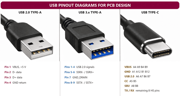
In the USB 2.0 USB pinout, D+ and D- form one differential pair. USB 3.x keeps those four legacy contacts and adds separate transmit and receive pairs plus a signal-return contact. USB Type-C duplicates several contacts for reversibility; on a USB 2.0-only receptacle, connect the two D+ contacts together and the two D- contacts together close to the receptacle, following the connector and controller guidance.
Do not tie CC1 and CC2 together in a USB pinout. A sink normally presents an Rd pull-down on each CC pin, while a source presents Rp; dual-role and Power Delivery designs need a suitable Type-C/PD controller. This part of the USB pinout determines attach detection, orientation, current advertisement, and cable communication.
USB Wiring Diagram and Color Codes
A USB wiring diagram maps cable conductors to the USB pinout, but conductor color is only a convention and must be verified by continuity testing or the cable drawing.
| Typical Color | Signal | Function | Design or Test Note |
|---|---|---|---|
| Red | VBUS | +5 V bus supply in conventional USB wiring | Check voltage at the connector under load; a cable can pass continuity yet have excessive voltage drop. |
| White | D- | Negative USB 2.0 data line | Keep paired with D+; do not swap the two conductors. |
| Green | D+ | Positive USB 2.0 data line | Maintain pair geometry and avoid long stubs from ESD parts or test pads. |
| Black | GND | Power and signal return | Verify low-resistance continuity before evaluating data traffic. |
| Bare / drain | Shield or drain | Cable shield termination | Treat as chassis/EMC hardware, not as a substitute for the GND conductor. |
| Other colors | SuperSpeed / CC / SBU | Vendor-specific high-speed or control conductors | No universal color code applies; use the cable assembly drawing and pin-to-pin test. |
Before connecting a custom cable to a prototype, use a current-limited supply and check each conductor against the intended USB pinout. A reversed VBUS/GND connection can damage the board immediately, while a D+/D- swap usually appears as failure to enumerate.
USB Connection Troubleshooting
USB troubleshooting is fastest when the USB pinout is checked in the order power, attach detection, signal continuity, signal integrity, and firmware enumeration.
Check the USB pinout view. Compare the assembled connector, CAD footprint, pin-one mark, and mating-face drawing. Mirrored Type-A, Micro USB, and USB Type-C footprints are common prototype failures.
Measure VBUS and ground. Confirm the expected VBUS at the receptacle and at the load, then check ground and shield continuity. Investigate connector contact resistance, fuse selection, cable loss, or inrush if voltage collapses under load.
Verify USB Type-C CC behavior. Check CC1 and CC2 resistor values, controller orientation detection, and whether the board is configured as source, sink, or dual-role. A USB 2.0-only Type-C device still needs a correct CC implementation.
Continuity-test the data paths. Check D+, D-, SuperSpeed pairs, ESD arrays, common-mode chokes if fitted, and any zero-ohm options. Confirm that protection parts have the correct pin mapping and are not rotated.
Inspect routing and assembly. Look for plane splits, long branches, excessive vias, pair asymmetry, solder bridges, voided connector tabs, and a damaged cable. Probe pads should not create uncontrolled stubs on high-speed lanes.
Separate hardware from firmware. If electrical checks pass, review clocking, PHY power rails, reset, pull-ups, descriptors, endpoint configuration, and host logs. Swap in a known-good short cable and a known-good host port before changing the PCB.
For intermittent faults, record which cable orientation, speed, load current, and host reproduce the issue. That evidence often reveals whether the USB pinout, Type-C orientation path, power path, or high-speed channel is responsible.
How a BOM Helps USB PCB Designers
A complete bill of materials turns the USB pinout and schematic into a buildable, reviewable interface rather than a connector symbol with missing support parts.
Prevents connector substitutions. Record the exact manufacturer part number, mounting style, contact count, plating, shell stakes, footprint revision, and USB pinout. Two visually similar USB Type-C receptacles can have different pad layouts or missing high-speed contacts.
Locks electrical roles. List CC resistors, USB PD controller, load switch, current-limit device, fuse, TVS array, and any VBUS discharge or overvoltage parts required by the chosen role.
Protects signal integrity. Capture the approved ESD array, optional common-mode choke, and zero-ohm configuration parts with packages and capacitance appropriate to the implemented data rate.
Improves sourcing and DFM. Add acceptable alternates only after checking footprint, pin mapping, height, insertion life, rated current, and reflow compatibility. A generic 'USB-C connector' BOM line is not sufficient.
Speeds failure analysis. Reference designators let engineers trace a faulty USB pinout path from connector to protection, controller, and power circuitry without guessing which production option was fitted.
Before release, run a BOM-to-schematic check: every USB pinout net should terminate at the intended component, and every populated component should have a verified footprint, value, voltage rating, package, and sourcing status.
Why PCBgogo Is a Trusted USB PCB Manufacturer
A correct USB pinout still needs disciplined fabrication and assembly because connector alignment, impedance control, protection placement, and solder-joint quality all affect field reliability.
One-stop delivery. PCBgogo provides PCB fabrication and PCBA assembly, including component sourcing and complete product services, so the connector, protection network, controller, and power path can be managed in one manufacturing workflow.
More than 10 years of manufacturing experience. That production background supports practical review of dense USB connector footprints and repeatable assembly requirements.
Automated SMT production. Advanced automated SMT lines help maintain placement consistency for ESD arrays, fine-pitch controllers, passives, and other parts surrounding the USB pinout.
Strict quality control. A controlled inspection process reduces the risk of solder bridges, insufficient joints, polarity errors, and connector-shell defects moving into final products.
Reliable impedance control. Accurate impedance control is essential for USB 2.0 and SuperSpeed differential pairs when the stackup and routing geometry are defined correctly in the design data.
Need to integrate a USB connector into your PCB design? Explore PCBgogo's full PCBA assembly service and advanced PCB manufacturing, or request a quote for a high-quality PCB or PCBA build.
PCBgogo - Reliable, High-Quality PCB Manufacturing
PCBgogo is a one-stop PCB and PCBA manufacturing factory, helping you save time and costs while ensuring consistent, reliable quality.
Get a Free Quote >
Summary
A reliable USB pinout design starts with the correct USB pinout, then validates connector orientation, protocol capability, power role, routing, protection, BOM, and assembly details. Treat the component drawing and implemented USB specification as the final design authority.
Frequently Asked Questions
Is USB-C the same as USB Type-C?
Yes. USB-C and USB Type-C refer to the same reversible connector family, but the connector name does not guarantee a particular data rate, video mode, or charging power.
How many pins are in a USB pinout?
The count depends on the connector: USB 2.0 Type-A and Type-B use four contacts, Mini and Micro USB 2.0 commonly use five, USB 3.x Type-A and Type-B use nine, SuperSpeed Micro-B uses ten, and a full USB Type-C receptacle uses 24.
Can I identify USB wires by color alone?
No. Red, white, green, and black are common for VBUS, D-, D+, and GND, but cable makers may use different colors. Verify the USB pinout with the cable drawing or a continuity test.
Does every USB Type-C port support 240 W?
No. Up to 240 W requires USB Power Delivery Extended Power Range plus a compliant source, sink, controller, connector, and marked cable rated for the required current and voltage. Many USB Type-C ports support much less power.
What should I check before releasing a USB PCB?
Check the connector view, footprint, USB pinout net mapping, CC implementation, VBUS protection, shell grounding, 90-ohm differential routing, ESD placement, BOM part numbers, and assembly access. Then test enumeration, current draw, cable orientation, and data transfer with known-good hosts and cables.