



 日本語
日本語
 한국어
한국어

SMT BOM: What Makes It Different From a Standard Bill of Materials
An SMT BOM lists the same components as any other bill of materials — but a pick-and-place machine can't run on a generic parts list the way a through-hole assembler can. Component orientation, package precision, and moisture sensitivity all become production-critical the moment a part is going down on a stencil-printed pad instead of through a drilled hole. This guide focuses on exactly what an SMT BOM needs that a standard BOM doesn't, and how it pairs with the other files your assembler actually runs the line from.
What Is an SMT BOM, Specifically?
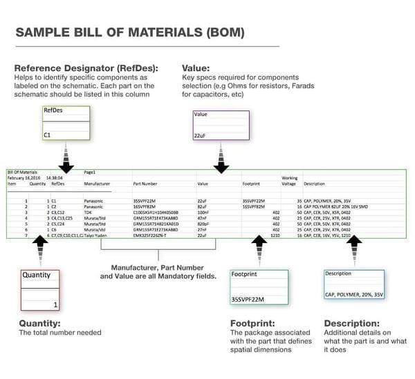
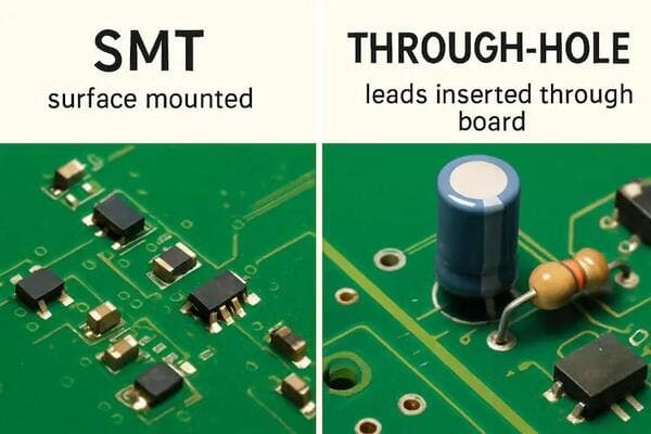
An SMT BOM is the version of a bill of materials prepared for a board that will be assembled using surface-mount technology — components placed and reflow-soldered directly onto pads on the board surface, rather than inserted through drilled holes. The component list itself looks similar to any BOM (reference designator, value, quantity, part number), but the supporting detail has to be precise enough for automated placement rather than a technician's judgment call.
The distinction matters because SMT assembly is machine-driven from end to end: a pick-and-place machine reads placement data, picks parts from tape-and-reel or tube packaging, and sets them onto solder paste with no manual correction step in between. If the BOM's package or orientation data is wrong, the machine places it wrong — there's no equivalent to a technician noticing a part looks off before soldering it in by hand.
SMT BOM vs. Standard/THT BOM: What Actually Changes
| Requirement | Through-Hole (THT) BOM | SMT BOM |
|---|---|---|
| Package tolerance | Looser — hole size and lead spacing have some mechanical give | Tight — footprint must match the stencil aperture and land pattern precisely |
| Orientation data | Often visually obvious (radial leads, DIP notch) | Must be explicit — many SMD packages give no visual cue without a marked BOM/CPL |
| Placement file dependency | Optional; hand-placed parts don't need X-Y coordinates | Required — CPL/centroid file with X-Y-rotation-side data per part |
| Moisture sensitivity | Rarely a factor | Common for fine-pitch ICs and BGAs; drives bake-out and storage |
| Minimum package size | Not applicable | Down to 0201 or 01005 on some lines, constrained by machine capability |
The BOM + CPL Relationship
This is the part most generic BOM guides skip, and it's the single biggest structural difference for SMT: the BOM tells the assembler what each component is, but a separate file — the centroid file, also called the CPL (component placement list) or pick-and-place file — tells the machine exactly where to put it. The BOM and the CPL have to reference the same reference designators consistently, or the placement machine has no way to reconcile the two.
A CPL typically includes:
Reference designator — matching the BOM and the schematic exactly.
X and Y coordinates — the part's center position on the board, usually referenced to a defined origin.
Rotation — the part's angle relative to the board outline, since most EDA tools and assembly houses use slightly different rotation conventions.
Side — top or bottom, for boards populated on both sides.
A mismatch between the BOM's reference designators and the CPL's — a renumbered part in one file but not the other — is one of the most common causes of placement errors flagged during file review, since the two documents are generated separately and don't always get updated together.
Fields an SMT BOM Needs That a Generic Field List Won't Mention
Orientation and polarity marking
Any component with a directional requirement — tantalum and electrolytic capacitors, diodes, ICs with a pin-1 indicator — needs its orientation captured somewhere the placement machine can read it, either as a BOM note or, more reliably, as rotation data in the CPL. A polarized capacitor placed backward is a functional failure, not a cosmetic one, and it's not always visible after reflow.
Moisture sensitivity level (MSL)
Fine-pitch ICs and BGA packages absorb ambient moisture, which can vaporize explosively during reflow and crack the package — an effect known as "popcorning." Components are rated MSL 1 through 6, with higher numbers requiring shorter floor life outside dry storage and a bake-out step if that floor life is exceeded. If your BOM doesn't flag MSL-sensitive parts, the assembler is working from datasheets alone to catch this, which is slower and easier to miss on a large BOM.
Tape-and-reel vs. cut-tape vs. tube packaging
SMT components are supplied in formats built for machine feeders — tape-and-reel being the standard for production runs, with cut-tape or tube packaging more common for prototype quantities. This doesn't need to be an explicit BOM field for most projects, but for larger production runs it's worth confirming with your assembler, since feeder setup time scales with the number of distinct reels being loaded.
Panel quantity vs. per-board quantity
When boards are assembled in a panel (multiple copies of the same design on one panel for efficiency), be explicit about whether BOM quantities are per single board or per panel. This is a common source of confusion on a first order — a per-board BOM quantity of "1" needs to be multiplied by the panel count during procurement, and an assembler will typically ask for clarification if it's ambiguous rather than assume.
Package Size and Machine Placement Capability
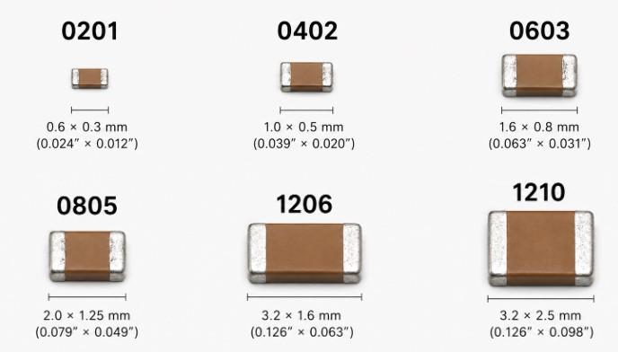
Not every assembly line can place every package size. 0201 and 01005 passive components are common enough in dense designs, but they require placement machines with the resolution and feeder precision to handle them reliably — smaller lines built around 0402 as a practical minimum may struggle with yield on anything smaller. If your BOM includes very small passives or fine-pitch (0.4mm or finer) QFN/BGA packages, it's worth confirming your assembler's placement capability for those specific packages before finalizing sourcing, rather than assuming any SMT line can run them.
Mixed SMT and Through-Hole BOMs
Many boards combine surface-mount and through-hole components — a connector or electrolytic capacitor mounted through-hole alongside a mostly SMT design. In a mixed BOM, it helps to make the placement method an explicit field per line, not just an assumption based on package type, since assembly typically happens in a specific sequence: SMT components are reflow-soldered first, then through-hole components are inserted and wave- or hand-soldered afterward. A BOM that doesn't distinguish which components belong to which stage can lead to a part being scheduled for the wrong process step.
How SMT BOM Data Feeds Stencil and Paste Design
The package data in your BOM isn't just informational — it directly shapes the stencil used to print solder paste. QFN packages with exposed thermal pads, for example, need a modified stencil aperture (often a stepped or windowed design) to control paste volume and avoid solder balling or voiding under the package. If the BOM's package field is vague or generic, stencil design decisions get made on assumptions rather than the actual part, which is one of the more preventable causes of paste-related defects. Running a DFM check before finalizing the design — PCBgogo checks footprint and package data against the layout during DFM review — catches this kind of package/footprint mismatch before a stencil is ever cut.
Common SMT-Specific BOM Errors
1. Missing polarity/orientation data — leads to backward-placed diodes or capacitors that pass placement but fail electrically.
2. BOM/CPL reference designator mismatch — a RefDes renumbered in one file but not the other, misaligning placement coordinates.
3. Unflagged MSL-sensitive parts — increases the risk of moisture-related package cracking if bake-out is skipped.
4. Ambiguous package data on exposed-pad packages (QFN, DFN) — leads to stencil apertures that don't match the actual thermal pad, causing paste voiding.
5. Per-board vs. per-panel quantity confusion — causes under- or over-ordering of components for a panelized run.
SMT BOM Example
A simplified SMT BOM row, with the fields specific to surface-mount assembly included:
| RefDes | Value | Package | MPN | Orientation/Polarity | MSL | Qty |
|---|---|---|---|---|---|---|
| C12 | 10μF, X7R, 16V | 0603 | GRM188R71C106KA73D | N/A | N/A | 1 |
| C15 | 22μF, Tantalum, 16V | Case B (3216) | TAJB226K016RNJ | + terminal per silkscreen | N/A | 1 |
| U2 | — | QFN-32, 5x5mm | STM32G031G8U6 | Pin 1 dot, per CPL rotation | MSL 3 | 1 |
| D3 | Schottky diode | SOD-123 | BAT54SW | Cathode band per CPL | N/A | 1 |
Frequently Asked Questions
Is an SMT BOM a different document from a regular BOM?
Not structurally — it's the same type of document, but built with SMT-specific detail: precise package data, orientation/polarity for directional parts, and MSL flags where relevant. The core fields (RefDes, value, quantity, MPN) are shared with any BOM.
Do I need a separate CPL file, or can the BOM include placement coordinates?
Most assembly workflows expect these as two separate files — the BOM for what each component is, and the CPL/centroid file for where it goes and at what rotation. Combining them into one document is possible but uncommon, since EDA tools generate them as separate exports by default.
What happens if I don't flag MSL-sensitive components?
The assembler may still catch it by cross-checking datasheets for fine-pitch ICs and BGAs, but it adds review time and risk on a large BOM. Flagging MSL directly in the BOM is faster and more reliable than relying on that manual check.
Can PCBgogo catch SMT-specific BOM issues before assembly?
PCBgogo runs DFM checking on submitted designs, which includes verifying footprint and package data against the layout — a useful check for exactly the kind of package/footprint mismatch that causes stencil and placement issues. For a full walkthrough of building the underlying BOM itself, see our guide on how to build a BOM.





