
SMD vs SMT: What's the Difference?
SMD and SMT are two of the most used terms in PCB manufacturing — but they mean very different things. SMD (Surface Mount Device) is a type of electronic component. SMT (Surface Mount Technology) is the process used to mount those components onto a PCB. This article breaks down what each term means, how they work together, and why it matters for your PCB project.
SMD vs SMT: The Core Difference
If you've ever seen these two terms used interchangeably, you're not alone — but they are not the same thing. SMD refers to what goes on the board; SMT refers to how it gets there.
What Does SMD Stand For?
SMD stands for Surface Mount Device. It refers to the electronic component itself — the physical part that gets placed on a PCB. SMDs have no long wire leads. Instead, they have small metal pads or short terminals that sit directly on the board surface.
Common examples include resistors, capacitors, diodes, transistors, and ICs.
What Does SMT Stand For?
SMT stands for Surface Mount Technology. It is the manufacturing process used to attach SMD components to a PCB. The SMT process includes solder paste printing, pick-and-place machine assembly, and reflow soldering.
SMT is how SMDs end up on the board — it is not a component.
Quick Comparison: SMD vs SMT
?? Key takeaway: SMD is the noun. SMT is the verb.
What Is SMD? A Complete Breakdown
An SMD is any electronic component designed to be mounted directly on the surface of a PCB — without needing drilled holes. SMDs are smaller, lighter, and better suited for automated assembly than older through-hole components.
?? Image suggestion: A close-up photo of a PCB populated with SMD components — resistors, capacitors, and ICs visible. Label a few components to show their package types (e.g., 0402 resistor, SOT-23 transistor).
Types of SMD Components
SMDs are broadly divided into two categories:
Passive SMDs do not consume or generate power on their own. They simply control the flow of current or store energy. Examples include:
Resistors
Capacitors
Inductors
Filters and couplers
Active SMDs consume power and can amplify or switch signals. Examples include:
Integrated circuits (ICs)
Transistors
Diodes
MOSFETs
There are also electromechanical SMDs — such as SMD connectors, switches, and relays — which have both electrical and mechanical functions.
Key Physical Characteristics of SMD Components
SMDs look and behave very differently from traditional through-hole parts:
No long leads — SMDs connect via flat pads or short terminals on the underside
Low profile — they sit close to the board surface, which reduces height
Shorter signal paths — less parasitic capacitance and inductance, which improves performance at high frequencies
Smaller footprint — typically about 1/10 the size of equivalent through-hole components
Dual-side mounting — SMDs can be placed on both sides of a PCB
These properties make SMDs ideal for compact, high-performance electronics like smartphones, wearables, and medical devices.
Common SMD Package Sizes
SMD components come in standardized package sizes. The naming system uses imperial dimensions (hundredths of an inch).
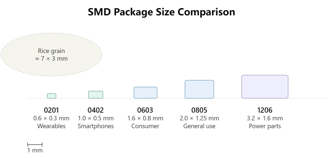
The smaller the package, the more challenging the assembly — requiring higher-precision pick-and-place machines and finer stencil printing.
What Is SMT? Detailed Explanation
SMT is the standard PCB assembly method used in modern electronics manufacturing. It replaced older manual assembly techniques in the 1980s and is now used across consumer electronics, automotive, medical, and aerospace industries.
Key Features of SMT
Fully automated — pick-and-place machines can place thousands of components per hour
High component density — components can be placed on both sides of the board
Consistent quality — automated optical inspection (AOI) catches placement and soldering defects
Cost-effective at scale — automation reduces labor costs significantly
Supports fine-pitch components — capable of handling packages as small as 01005
The Full SMT Process
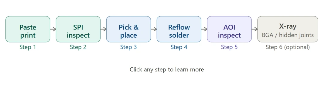
A standard SMT assembly line follows these steps:
Step 1 — Solder Paste Printing A metal stencil is aligned over the bare PCB. Solder paste (a mix of flux and tiny solder particles) is pressed through the stencil openings onto the pads.
Step 2 — Solder Paste Inspection (SPI) An automated machine checks paste volume, shape, and alignment. This step catches printing errors before any components are placed.
Step 3 — Pick-and-Place A machine picks SMD components from reels or trays and places them precisely onto the solder paste. Modern machines can place 20,000–100,000 components per hour.
Step 4 — Reflow Soldering The board travels through a reflow oven. The temperature profile melts the solder paste and creates a permanent bond between the SMD and the PCB pad.
Step 5 — Automated Optical Inspection (AOI) A camera system scans the board to verify correct placement and solder joint quality. Defects are flagged for rework.
Step 6 — (Optional) X-Ray Inspection For packages like BGA (Ball Grid Array) where solder joints are hidden beneath the component, X-ray inspection verifies joint quality.
For a deeper look at the full SMT line setup, see our SMT Assembly Process Guide.
Can SMD Exist Without SMT?
Technically, yes — but not efficiently.
SMD components can be hand-soldered using a fine-tip iron, hot air gun, and tweezers. This is common for prototyping, repair work, or very low-volume production. However, hand-soldering SMDs — especially tiny 0402 or 0201 packages — is slow, requires skilled technicians, and is prone to errors.
SMT cannot exist without SMDs. The entire process is built around mounting surface-mount devices.
In practice, SMT and SMD are always used together. The automation and precision of SMT make SMD components viable at production scale. And the compact size of SMDs is what makes the SMT process worthwhile in the first place.
Conclusion: How PCBGOGO Supports SMD and SMT Assembly
Understanding the difference between SMD and SMT helps you make better decisions at the design and procurement stage — from choosing the right package sizes to specifying the right assembly process.
At PCBGOGO, we offer full SMT assembly services with advanced pick-and-place equipment capable of handling packages down to 01005. Our SMT lines include:
Automated solder paste printing and SPI inspection
High-speed and precision pick-and-place machines
Lead-free reflow soldering (RoHS compliant)
AOI and X-ray inspection for quality assurance
Support for a wide range of SMD packages — passive, active, and electromechanical
Whether you need a small prototype run or large-scale production, our team can guide you through the full process — from Gerber files to finished PCBA.
[Get an instant SMT assembly quote →]
Frequently Asked Questions
Are SMD and SMT the same thing?
No. SMD (Surface Mount Device) is the electronic component. SMT (Surface Mount Technology) is the process used to mount that component onto a PCB. They work together but refer to different things.
Can SMD components be hand soldered?
Yes, but it's challenging. Small SMD packages like 0402 or 0201 require a fine-tip soldering iron, hot air station, tweezers, and magnification. Hand soldering is fine for prototyping or rework, but not practical for production.
Is SMT better than THT?
It depends on the application. SMT is better for compact, high-volume, automated assembly. THT (Through-Hole Technology) is better for components that need strong mechanical connections — like large connectors or components that face physical stress. Many boards use both methods together.
What does SMD mean on a PCB?
On a PCB, SMD refers to any component mounted on the board surface without through-holes. When a PCB layout file labels a footprint as "SMD," it means the pads are surface pads, not plated through-holes.
What is the difference between SMD and DIP components?
DIP (Dual In-line Package) is a through-hole component format with two rows of pins that pass through the PCB. SMD components sit on the surface with no pins going through the board. SMDs are smaller, lighter, and better for automated assembly. DIP packages are larger and easier to handle manually — making them common in prototyping and education.
What industries rely most on SMT manufacturing?
SMT is used across virtually all electronics industries. The highest-volume users include consumer electronics (smartphones, laptops, tablets), automotive electronics (ECUs, sensors, infotainment), medical devices (monitors, diagnostic tools), and telecommunications equipment. Aerospace and defense also use SMT, with extra requirements around reliability and inspection standards like IPC-A-610 Class 3.

