



 日本語
日本語
 한국어
한국어

Renewable Energy PCB: How PCBs Power the Clean Energy Revolution
Every solar inverter, wind turbine controller, and battery management system has one thing in common: a printed circuit board doing the heavy lifting behind the scenes. As renewable energy capacity scales rapidly worldwide, the demands placed on these PCBs are growing just as fast. Here's a practical look at how PCBs function in clean energy systems, what it takes to build them right, and why getting the specs right from the start matters more than ever.
Why Renewable Energy Systems Depend on High-Performance PCBs
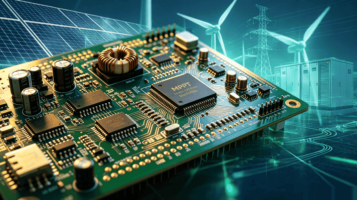
Renewable energy isn't just a power source — it's a complex network of sensors, controllers, converters, and communication modules, all coordinated by electronics. PCBs serve as the backbone of that coordination. In a solar installation, for instance, PCBs inside the Maximum Power Point Tracking (MPPT) controller continuously adjust current and voltage to extract peak efficiency from the panels, regardless of weather conditions.
Wind turbines use PCBs to manage pitch and yaw control — the systems that physically orient the blades and nacelle for optimal performance. Battery energy storage systems (BESS) rely on PCBs for cell balancing, State of Charge (SoC) monitoring, and thermal protection logic. In each case, PCB failure isn't just an inconvenience; it can mean significant energy losses, equipment damage, or safety risks.
The table below shows how PCBs map to specific renewable energy sectors:
undefined
| Renewable Energy Sector | PCB Role | Key PCB Requirements |
|---|---|---|
| Solar (PV) Systems | MPPT & inverter control | High Tg, thermal management, moisture resistance |
| Wind Turbines | Pitch & yaw control, power conversion | Vibration resistance, conformal coating |
| Battery Energy Storage (BESS) | BMS logic & cell balancing | Compact multilayer, heavy copper, high reliability |
| Hydropower & Tidal | Generator control, monitoring | Humidity resistance, robust connectors |
| Smart Grid / EV Charging | Power conversion & communications | EMI shielding, high-frequency signal integrity |
Key Design Challenges for Renewable Energy PCBs
Designing a PCB for a renewable energy application is fundamentally different from designing one for consumer electronics. The operating environments are harsher, the reliability expectations are longer (often 20–25 years), and the consequences of failure are more severe. These are the four challenges that matter most:
1. Thermal Management
Power electronics in solar inverters and EV chargers generate significant heat. Without proper thermal dissipation, components degrade faster and efficiency drops. Aluminum-core PCBs (MCPCBs) and high-thermal-conductivity laminates are often specified to channel heat away from critical components effectively.
2. Vibration and Mechanical Stress
Wind turbines vibrate constantly during operation. PCBs inside nacelles must maintain solder joint integrity and trace adhesion despite ongoing mechanical stress. This typically calls for robust laminate materials, careful via design, and sometimes conformal coating to protect against fatigue cracking.
3. Environmental Exposure
Outdoor renewable energy systems face humidity, UV exposure, salt air (in coastal and offshore installations), and wide temperature swings. Moisture absorption above 0.2% can compromise electrical insulation and cause corrosion over time. Conformal coatings and moisture-resistant laminates like polyimide are standard countermeasures.
4. High-Frequency Signal Integrity
Modern inverters and smart grid communication circuits operate at high switching frequencies — often above 100 kHz. At these frequencies, standard FR4's dielectric constant (~4.5) and dissipation factor can introduce meaningful signal loss. Engineers often switch to low-Dk materials (Rogers or PTFE-based laminates) for high-frequency sections of the design to preserve signal quality.
Choosing the Right PCB Materials for Clean Energy Applications
Material selection is one of the most important decisions in renewable energy PCB design. The wrong choice can shorten service life by years; the right one makes a system that performs reliably for decades with minimal maintenance.
| PCB Material | Key Property | Best For |
|---|---|---|
| High-Tg FR4 (Tg ≥170°C) | Thermal stability, cost-effective | Solar inverters, moderate heat |
| Aluminum-core (MCPCB) | High thermal conductivity (1–3 W/m·K) | LED drivers, heat-dense power boards |
| Polyimide | Extreme temperature range (-200°C to +300°C) | Offshore wind, harsh outdoor installations |
| Rogers / PTFE | Low Dk (2.2–3.5), low Df | High-frequency control & communication circuits |
| Heavy Copper (≥3 oz) | High current carrying capacity | Battery management, EV charging stations |
For most solar inverter applications, high-Tg FR4 (glass transition temperature ≥170°C) offers a practical balance of cost and performance. Where extreme heat is involved — such as utility-scale battery storage in hot climates — polyimide materials provide superior stability across a much wider thermal range (?200°C to +300°C).
Heavy copper PCBs (3 oz copper or more) are particularly relevant for battery management systems and EV charging stations, where high current paths need to be accommodated without trace overheating. The heavier copper allows for wider current-carrying capacity without increasing board footprint significantly.
PCB Types Used Across Renewable Energy Platforms
There's no single PCB type that covers all renewable energy applications. Here's how different board configurations show up in the field:
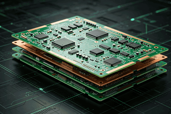
Multilayer PCBs (4–12 layers): Used in inverter control boards and BMS where circuit density is high and signal routing requires dedicated ground and power planes for noise isolation.
Aluminum-core PCBs (MCPCBs): Dominant in LED drivers and components where thermal dissipation is the primary concern. Thermal conductivity of 1–3 W/m·K vs. standard FR4's 0.3 W/m·K makes a significant difference.
Flex and Rigid-Flex PCBs: Used in space-constrained or form-factor-sensitive parts of wind turbine assemblies and portable monitoring devices. They allow three-dimensional routing that rigid boards can't achieve.
Heavy Copper PCBs: Common in power conditioning and high-current distribution boards for battery storage systems and EV charging infrastructure.
High-Frequency PCBs (Rogers, PTFE): Specified for communication interfaces, smart metering, and any portion of a design where the switching or signaling frequency demands low-loss dielectric properties.
Quality and Reliability Standards for Renewable Energy PCBs
Renewable energy systems are typically designed for a 20–25 year service life. That lifespan expectation raises the bar for PCB quality considerably compared to commercial electronics, where a 5–7 year lifecycle is common. Several standards guide design and manufacturing quality:
IPC-6012: Qualification and performance specification for rigid PCBs, covering dimensional, visual, and electrical requirements. Class 3 compliance is often specified for energy-critical boards.
IPC-A-600: Acceptability standard for printed boards, used to assess surface and internal quality.
UL 94 V-0 flammability rating: Required for boards used in enclosed power electronics where fire resistance is a safety concern.
RoHS compliance: Lead-free solder and materials are standard practice across most renewable energy deployments, particularly in markets with strict environmental regulations.
For engineers and procurement teams sourcing PCBs for clean energy projects, working with a manufacturer that understands these standards — and can demonstrate compliance — is essential. At PCBgogo, we manufacture PCBs to IPC Class 2 and Class 3 specifications, with full traceability and rigorous electrical testing on every order. Whether you need high-Tg multilayer boards for a solar inverter or heavy copper PCBs for a battery management system, our production capabilities are built to meet the reliability demands that renewable energy applications require.
PCB Trends Shaping the Future of Renewable Energy
As renewable energy technology evolves, so do the PCBs that power it. A few trends are worth watching:
Wide-bandgap semiconductors (SiC, GaN): These components switch faster and at higher voltages than silicon, pushing inverter efficiency above 99%. They also require PCBs with even better thermal management and lower parasitic inductance than traditional designs.
Increased power density: As inverters get smaller and more powerful, PCB designs must pack more functionality into tighter footprints — driving adoption of HDI (High Density Interconnect) PCBs with microvias and finer trace geometries.
Embedded components: Placing passive components directly inside PCB layers reduces parasitic effects and board size, a technique gaining traction in next-generation inverter designs.
Sustainability in PCB manufacturing: Bio-resin substrates and halogen-free laminates are seeing increased adoption as the renewable energy sector applies sustainability standards to its supply chain as well as its end products.
Getting Your Renewable Energy PCB Right
The performance of a renewable energy system often comes down to decisions made during PCB design and manufacturing. Material selection, thermal strategy, layer stack-up, and compliance all interact — and errors at any one of these points can compromise an installation designed to run for two decades.
For project teams working on solar, wind, storage, or grid infrastructure, the best approach is to engage your PCB manufacturer early in the design cycle. Understanding what materials are available, what tolerances are achievable, and what testing protocols are in place helps you make design decisions with full visibility into manufacturability and long-term reliability.
If you're working on a renewable energy PCB project and need a reliable manufacturing partner, feel free to contact us. Our engineering team will provide tailored, high-reliability manufacturing solutions to support your project from design to production.





