
 日本語
日本語
 한국어
한국어

PCB V Scoring Guide: Design Rules, Depth & Clearance
KEY DEFINITION V-Cut, also called V-Scoring, is a PCB panelization method that cuts V-shaped grooves one-third of the way through the board from both top and bottom surfaces along straight lines, creating breakaway channels that allow individual boards to be separated from the production panel after assembly. It is the fastest and most cost-effective depaneling method but is limited to rectangular board outlines and straight cut paths that run the full length of the panel.
Panelize twenty boards onto a single panel, run it through reflow, and you still need twenty separate, undamaged boards on the other side. That last step, splitting the panel apart, is where a lot of avoidable defects happen. V-cut looks almost too simple: cut a groove, snap along the line, done. But get the depth, the angle, or the clearance from copper wrong, and that same groove becomes the reason an MLCC cracks six months later in the field. This guide covers what V-cut actually is, how the cut is made, and the design rules that keep it safe to use.
What Is PCB Panelization?
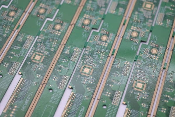
PCB panelization means arranging multiple board designs, usually identical copies of the same board, onto one larger panel before it goes through fabrication and assembly. Instead of handling a single small board through solder paste printing, pick-and-place, and reflow, the SMT line processes one panel that might carry twenty, forty, or more boards at once. Panelization exists because assembly equipment is built around consistent panel sizes and rigid, flat edges for gripping and transport, not loose or oddly shaped individual boards.
Once assembly finishes, the boards still have to be separated from the panel and from each other without damaging components soldered near the edges. That separation step is called depaneling, and V-cut is one of the two methods used to do it, the other being tab-routing with mouse bites. Which method a panel uses gets decided during design, not after the boards come off the assembly line, so it's worth understanding how V-cut physically works before finalizing a panel layout.
How V-Cut Actually Works
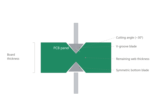
V-cut, also called V-scoring, works by mechanically weakening the board along a straight line instead of cutting all the way through it. A rotating circular blade, angled to produce a V-shaped profile, runs the length of the panel and cuts a groove partway into the board from the top surface. A second blade, or the same blade on a return pass, cuts a matching groove from the bottom, directly opposite the first. Neither groove goes all the way through the board, so a thin layer of material remains in the middle. That remaining layer is called the residual thickness, or simply the web, and it's what holds the whole panel together as one piece.
The web has to do two conflicting jobs. Through fabrication, transport, and SMT assembly, it needs to be thick enough that the panel survives handling and reflow without any board breaking off early. During depaneling, once assembly is finished, it needs to be thin enough that an operator or depaneling machine can snap along the scored line cleanly, without tearing the fiberglass or stressing solder joints on components near the edge. Balancing those two requirements is really the whole design problem behind V-cut, which is why the exact depth, angle, and clearance matter as much as they do (the specific numbers are covered in the design rules below).
Is V-Cut Right for Your Board?
V-cut panelization dominates production for a reason: it is fast, requires no custom routing paths, and leaves a clean edge with minimal fiberglass fraying compared to tab-routed breakaway tabs. But its applicability is narrower than most designers assume. Here is when it actually fits, and when it does not.
V-cut works well when:
The board is rectangular with straight, uninterrupted edges on all four sides. This is the sweet spot. Grooves can run across the entire panel in both X and Y directions, and an operator can separate boards with a depaneling saw in under five seconds per cut line.
The panel is a simple array of identical rectangular boards. V-cut lines form a grid, with each board sharing a groove with its neighbor. This is the highest-yield panel configuration in PCB manufacturing and accounts for most V-cut production volume.
The board is thicker than 1.0 mm and has no heavy components near the cut edge. The groove leaves a thin web of material, the residual thickness, that has to survive handling until depaneling. Boards thinner than 1.0 mm, or boards with connectors and transformers mounted within 5 mm of the line, don't leave enough material in that web to avoid premature cracking.
V-cut doesn't work when any of these apply:
The board isn't rectangular. Curved edges, notches, or irregular outlines can't follow a straight V-cut path.
The board is thinner than 0.8 mm. The residual web becomes too fragile.
Components sit within 1.0 mm of the board edge. The depaneling saw will hit them, and the mechanical stress of separation can crack solder joints on nearby MLCCs and BGAs.
In any of these three cases, tab-routing with mouse bites is the correct alternative.
The Five Design Rules That Make or Break a V-Cut Panel
Every V-cut failure I have seen on a production line traces back to one of these five rules being broken. They are not complex, but they are non-negotiable.
1. Residual thickness: one-third of the total board thickness. The V-cut blade cuts a groove approximately one-third of the way through the board from the top, and a second blade or the same blade in a second pass cuts another one-third from the bottom. The remaining third in the middle is the web that holds the board together until depaneling. For a standard 1.6 mm board, that means approximately 0.5 mm of material remains. Cut too deep, and boards snap during handling or reflow. Cut too shallow, and the depaneling operator applies excessive force, cracking components and delaminating inner layers. The IPC-2221 standard references edge clearance and mechanical integrity requirements that drive this one-third rule, though it does not codify the ratio itself as a hard specification.
2. Clearance from V-cut centerline to copper: 1.0 mm minimum. The V-cut blade has a physical width at the board surface of approximately 0.8 mm to 1.2 mm, depending on the blade angle and wear condition. Add the positional tolerance of the scoring machine (typically plus or minus 0.15 mm), and a copper feature placed closer than 1.0 mm from the V-cut centerline risks being cut into during scoring. This is especially dangerous for inner layer copper on multilayer boards, where the damage is invisible until the board is depaneled and the exposed copper creates a short or a corrosion site. For controlled impedance traces, increase this clearance to 2.0 mm. The impedance discontinuity at a cut edge is already problematic; a partially scored trace is a guaranteed failure.
3. V-cut angle: 30 degrees is standard, 45 degrees for thick boards, 60 degrees for thin. The V-cut blade angle determines the groove profile and the force required for depaneling. A 30-degree blade produces a narrow groove with a sharp apex, suitable for standard 1.6 mm FR-4. A 45-degree blade produces a wider groove with more material removed, reducing depaneling force on thicker boards (2.0 mm and above). A 60-degree blade is used for thin boards (1.0 mm to 1.2 mm) where the groove must be shallow and wide to leave enough residual material. Most fabricators stock 30-degree blades as their default and use 45-degree or 60-degree blades only on request, so specify the angle on your fabrication drawing if your board thickness falls outside standard range.
4. V-cut lines must run the full length of the panel. This is the most commonly misunderstood V-cut constraint. A V-cut groove is created by a circular scoring blade spinning at high speed while the panel moves linearly beneath it. The blade cannot start or stop mid-panel. If your design requires a V-cut that stops 10 mm before the board edge, V-cut cannot do it. The solution is either to accept the V-cut running the full length and add a process edge rail, or to switch to tab-routing for that section and use V-cut only for the uninterrupted cuts.
5. Process edge rails: add 10 mm to 12 mm on two opposite sides. Automated SMT assembly lines grip the panel by its edges for transport through printers, placement machines, and reflow ovens. If V-cut grooves run all the way to the panel edge, the gripping mechanism can snap the board at the groove during handling. Adding a solid process rail of 10 mm to 12 mm on two opposite sides of the panel provides a safe gripping surface, a location for fiducial marks and tooling holes, and a mechanical buffer that keeps the V-cut grooves in compression during assembly.
How the Fab Shop Executes V-Cut: What Happens After You Submit Files
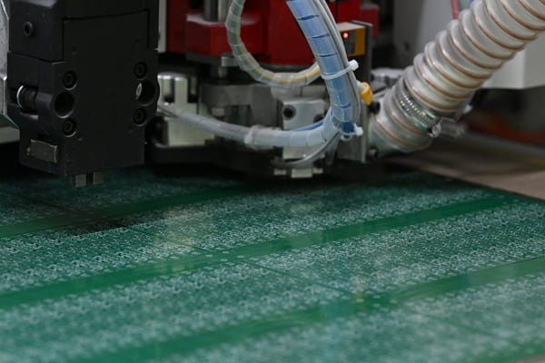
Understanding this sequence matters because it's where your design choices turn into cost or risk. Once your Gerber files land at the fabricator, the CAM engineer reviews the outline and panel drawing and works through three steps before the panel goes to production.
Step 1: Set the blade depth
The depth is based on the panel's actual measured thickness after lamination and plating, not the nominal design number. A board designed at 1.6 mm might measure 1.55 mm or 1.68 mm depending on copper weight and lamination pressure. The operator measures it with a micrometer and sets the blade to hit the one-third residual target on each side. This is also why specifying residual thickness directly on the drawing, for example "residual web thickness 0.50 mm ± 0.10 mm," gives the fabricator more to work with than just writing "V-cut, 30 degrees."
Step 2: Sequence the cuts
For a grid panel, the blade scores every line in one direction first, then the panel rotates 90° and the perpendicular lines get scored. Doing it this way, rather than alternating directions, keeps the uncut direction rigid while the other is being cut. That produces a more dimensionally stable panel and avoids the cumulative bow that comes from switching back and forth.
Step 3: Check against acceptance standards
The relevant standards are IPC-6012 for rigid board performance and IPC-A-600 for post-fabrication acceptability. Neither defines V-cut quality directly, but both cover the edge condition: no exposed inner-layer copper at the cut, no delamination beyond 0.5 mm from the edge, and no fiberglass protrusions that would interfere with component placement or handling. PCBgogo builds this check directly into its CAM review, verifying the distance from the centerline to the nearest copper on every layer before a panel is approved. That step catches clearance violations that electrical DRC has no way of seeing, since DRC doesn't know where the blade is going to travel.
V-Cut vs. Tab-Routing: How to Choose Without Guessing
The choice between V-cut and tab-routing is not a matter of preference. It is a mechanical constraint driven by board shape, component placement, and edge quality requirements.
| Criterion | V-Cut (V-Scoring) | Tab-Routing |
|---|---|---|
| Board shape | Rectangular only | Any shape |
| Edge quality after depaneling | Smooth, minimal fraying | Rough edge with mouse-bite nubs; requires sanding |
| Depaneling speed | Under 5 sec per cut line | 30 sec to several minutes per board |
| Tooling cost | Low (standard blade) | Low to moderate (custom router program) |
| Minimum board thickness | 1.0 mm (0.8 mm with 60° blade) | 0.4 mm (standard) |
| Component proximity to edge | 2.0 mm minimum from V-cut line | 1.0 mm from routed edge |
| Non-rectangular boards | Not possible | Standard |
| Relative cost per board | $0.05 to $0.15 | $0.25 to $0.50 |
The crossover rule is simple. If your board is rectangular, your panel is a grid, and your components sit more than 2.0 mm from every board edge, V-cut is the correct choice and will cost less than tab-routing. If any of those three conditions fails, start with tab-routing and add V-cut only for the straight cuts where it applies. Hybrid panels using V-cut for the straight grid lines and tab-routing for irregular perimeter segments are common in medium-complexity designs and most fabricators support them.

Frequently Asked Questions
What is the difference between V-cut and V-Scoring?
They are the same process. "V-Cut" and "V-Scoring" are used interchangeably in the PCB industry to describe the mechanical scoring of V-shaped grooves into a panel for later depaneling. Some fabricators use "V-Scoring" to refer to the equipment and "V-Cut" to refer to the resulting groove, but the terms are functionally identical.
Can V-cut be used on flexible PCBs or rigid-flex boards?
No. Flexible and rigid-flex PCBs use polyimide substrates that do not fracture cleanly along a V-cut line the way FR-4 does. The scoring blade tears the flexible material rather than cutting it cleanly, and the residual web in a flexible circuit is too elastic to snap during depaneling. Laser depaneling or routing is the correct method for flex and rigid-flex boards.
How close can components be placed to a V-cut line?
A minimum of 2.0 mm from the V-cut centerline to the nearest component body. This accounts for the scoring blade width, positional tolerance, and the board flexure zone during depaneling. Multilayer ceramic capacitors (MLCCs) are especially sensitive to bending stress. An MLCC placed within 5 mm of a V-cut line risks microcracking that passes electrical test but fails in the field after thermal cycling.
How much does V-cut panelization cost compared to tab-routing?
V-cut is consistently the lower-cost option. The equipment is simpler, the tooling is a standard consumable blade rather than a custom router program, and the depaneling cycle time is measured in seconds rather than minutes. For a typical 4-layer rectangular board in a 4x5 grid panel, V-cut adds approximately $0.05 to $0.15 per board to the panelization cost. Tab-routing for the same panel adds $0.25 to $0.50 per board. The difference compounds with panel complexity and production volume.
Can I mix V-cut and tab-routing on the same panel?
Yes. This is called hybrid panelization and it is standard practice for boards that have a rectangular overall shape but contain a non-rectangular feature on one edge (a connector overhang, a curved corner, a mounting tab). The straight edges use V-cut, and the irregular edge uses tab-routing with mouse bites. Most fabricators, including PCBgogo, support hybrid panelization without additional tooling charges beyond the standard routing fee.
Conclusion
V-Cut panelization is the simplest, fastest, and least expensive way to prepare rectangular PCBs for automated assembly and depaneling. It works because the physics are simple: cut a groove, leave a web, snap cleanly. But the design rules are strict and the failure modes are unforgiving.
If your board is rectangular, thicker than 1.0 mm, and has no components within 2.0 mm of any edge, V-cut is almost certainly your answer. Specify the residual thickness on your fabrication drawing, keep copper 1.0 mm away from the V-cut centerline, add process edge rails, and send the panel drawing to your fabricator for review before you generate final Gerber files. That last step, sending the panel drawing early, catches the clearance violation that your DRC will never see and prevents the kind of respin that costs you a week of schedule and thousands of dollars in fabrication charges.
Visit PCBgogo to upload your panel design and get a free DFM review before your next production run.





