
 日本語
日本語
 한국어
한국어

Microcontroller PCB Design Guide: Layout & Checklist
Every smart device, from a simple thermostat to an advanced industrial controller, relies on a microcontroller to process inputs, execute instructions, and control outputs. Although modern microcontrollers are incredibly powerful, their performance depends heavily on how they are integrated into the PCB.
A well-designed microcontroller PCB can improve reliability, reduce electromagnetic interference, and simplify manufacturing. This guide explains the most common types of microcontrollers, how they are used in PCB design, and the layout practices that help engineers build stable, production-ready systems.
What Is a Microcontroller?
A microcontroller is a compact integrated circuit that combines a processor core, memory, and input/output peripherals on a single chip. Unlike a general-purpose processor, a microcontroller is designed to perform specific control tasks within embedded systems.
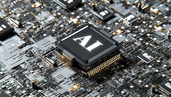
A typical microcontroller includes:
· CPU core
· Flash memory
· RAM
· GPIO pins
· Timers and counters
· Communication interfaces such as UART, SPI, I2C, USB, or CAN
· Analog-to-digital converters (ADCs)
Because all these functions are integrated into one device, microcontrollers offer a cost-effective solution for controlling electronic products.
Types of Microcontrollers
Microcontrollers can be categorized according to architecture, word size, and application requirements.
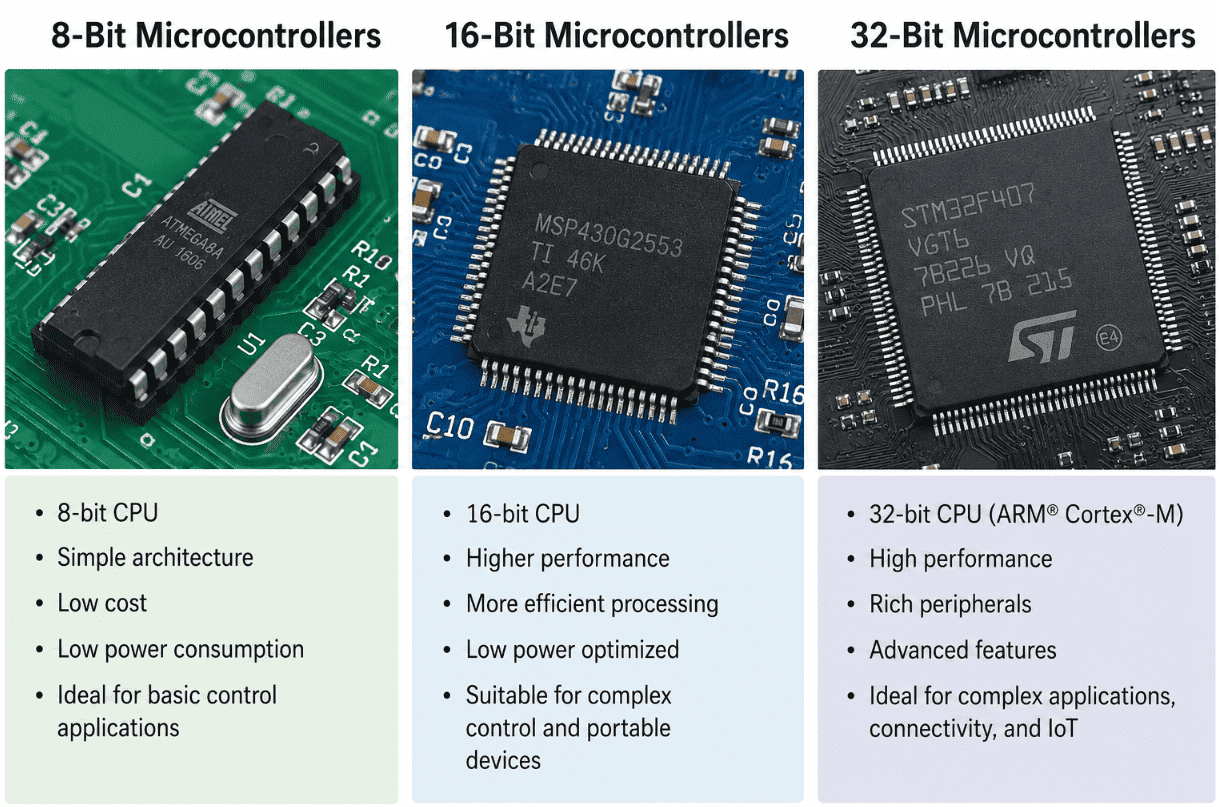
1. 8-Bit Microcontrollers
These devices are commonly used in simple control applications where cost and power consumption are primary concerns.
Examples include:
· ATmega328P
· PIC16 Series
· 8051 derivatives
Typical applications:
· Home appliances
· Basic automation
· Consumer electronics
2. 16-Bit Microcontrollers
16-bit MCUs offer improved processing capability while maintaining low power consumption.
Examples include:
· MSP430 Series
· PIC24 Series
Typical applications:
· Medical devices
· Energy monitoring systems
· Industrial controls
3. 32-Bit Microcontrollers
Modern embedded products increasingly use 32-bit devices due to their performance and peripheral integration.
Examples include:
· STM32 Series
· ESP32
· NXP LPC Series
· SAM Series
Typical applications:
· IoT devices
· Automotive electronics
· Robotics
· Industrial automation
The table below provides a quick comparison of 8-bit, 16-bit, and 32-bit microcontrollers in terms of performance, cost, and typical applications:
| Type | Processing Power | Cost | Typical Applications |
|---|---|---|---|
| 8-bit | Low | Low | Appliances, sensors |
| 16-bit | Medium | Medium | Medical and industrial systems |
| 32-bit | High | Medium to High | IoT, automotive, robotics |
How Microcontrollers Work on a PCB
Understanding the role of the MCU within the system makes PCB design decisions easier.
A microcontroller (MCU) serves as the brain of a PCB, collecting data from sensors, executing programmed instructions, and controlling outputs such as displays, motors, relays, and communication modules.
On a typical board, the MCU connects and coordinates multiple subsystems:
Power management circuits
Sensors and data acquisition devices
Communication interfaces (UART, SPI, I2C, CAN, Ethernet)
External memory
Human-machine interfaces (buttons, displays, LEDs)
Because every subsystem depends on the MCU, proper PCB design is essential for stable operation, signal integrity, and long-term reliability.
Microcontroller PCB Design Workflow
Selecting the right MCU is only the first step. Successful projects follow a structured design process.
Step 1: Define System Requirements
Determine:
Processing requirements
Memory requirements
Power budget
Communication interfaces
Operating environment
These requirements narrow down the list of suitable microcontrollers.
Step 2: Create the Schematic
The schematic should include:
Power supply circuits
Clock sources
Reset circuitry
Programming interface
Communication peripherals
At this stage, engineers should verify all manufacturer recommendations before moving to layout.
Step 3: Plan Component Placement
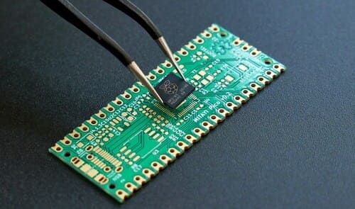
Component placement is one of the most important stages of microcontroller PCB design:
Decoupling capacitors close to power pins
Crystals near oscillator pins
High-speed interfaces away from noisy power circuits
Connectors along board edges when possible
Good placement often eliminates routing problems before they occur.
Step 4: Route Critical Signals
After placement is finalized, routing can begin.
Priority should be given to:
Clock signals
High-speed interfaces
Analog traces
Power distribution
Maintaining short signal paths improves both signal integrity and EMC performance.
Microcontroller PCB Layout Best Practices
Once the schematic is complete, attention shifts to microcontroller PCB layout.
Keep Decoupling Capacitors Close
Each power pin should have a dedicated bypass capacitor positioned as close as possible to the MCU package.
This minimizes transient voltage fluctuations and helps maintain stable operation.
Create a Continuous Ground Plane
A solid ground plane reduces noise and provides a low-impedance return path for signals.
Ground plane interruptions can create unwanted EMI problems and signal integrity issues.
Separate Analog and Digital Sections
Mixed-signal designs often include sensitive analog circuitry.
Keeping analog circuits away from noisy digital traces improves measurement accuracy and reduces interference.
Minimize Clock Trace Length
Clock signals generate significant electromagnetic emissions.
Short trace lengths help reduce EMI and improve signal quality.
Design for Manufacturability
Engineers sometimes focus exclusively on electrical performance and overlook manufacturing requirements.
A manufacturable layout should include:
Adequate component spacing
Proper solder mask clearance
Test points for debugging
Consistent trace widths
These considerations simplify assembly and testing.
Common Microcontroller PCB Design Mistakes
Many prototype failures can be traced back to a few common layout errors:
| Mistake | Potential Consequence |
|---|---|
| Poor decoupling capacitor placement | Power instability and random resets |
| Inadequate grounding | Noise and EMI issues |
| Long clock traces | Signal degradation and emissions |
| Narrow power traces | Voltage drop and overheating |
| Poor crystal placement | Startup and timing failures |
| Ignoring thermal considerations | Reduced reliability and lifespan |
Avoiding these issues early can significantly reduce debugging time.
Avoiding these issues early can significantly reduce debugging time.
Design Checklist Before Manufacturing
Before releasing a design for production, perform the following checks.
Power rails meet MCU requirements
Decoupling capacitors are correctly positioned
Crystal placement and routing follow recommendations
Ground planes remain continuous
Design rule checks (DRC) pass successfully
Programming and debugging interfaces are accessible
Thermal performance has been evaluated
Manufacturing clearances meet fabrication requirements
Completing this checklist can significantly reduce prototype failures.
Once your microcontroller PCB design has passed review, the next step is fabrication. PCBgogo supports PCB manufacturing and assembly services, making it convenient to move from design validation to prototype production using the same set of manufacturing files.
FAQs
What is a microcontroller?
A microcontroller is an integrated circuit that combines a processor, memory, and peripherals on a single chip. It is designed to control specific functions within embedded systems.
What are the main types of microcontrollers?
The most common categories are 8-bit, 16-bit, and 32-bit microcontrollers. Each offers different levels of processing performance and complexity.
Why is microcontroller PCB layout important?
PCB layout affects signal integrity, EMI performance, thermal behavior, and overall reliability. Even a powerful MCU can perform poorly on a poorly designed board.
What is the best microcontroller for beginners?
Popular beginner-friendly options include the ATmega328P, ESP32, and STM32 development boards because of their large communities and extensive documentation.
How close should decoupling capacitors be to a microcontroller?
They should be placed as close as possible to the MCU power pins. Short connections reduce noise and improve power stability.
Conclusion
Microcontrollers serve as the brains of modern electronic products, but achieving reliable performance requires more than selecting the right chip. By understanding the different types of microcontrollers and following proven microcontroller PCB layout practices, engineers can create designs that perform reliably from prototype through production.





