



 日本語
 한국어

Laser Drilling vs Mechanical Drilling for PCBs
QUICK ANSWER
Mechanical drilling is the economical choice for through holes, component leads, and mounting holes. Laser drilling creates the small, shallow microvias used in HDI routing. Many boards need both: conventional drills for full-depth connections and lasers for fine-pitch BGA escape.
Introduction
The laser drilling vs mechanical drilling decision affects routing density, plating reliability, stackup, lead time, and price. The right choice depends on hole diameter, depth, material, and production volume rather than on one process being universally better.
What Is Mechanical Drilling
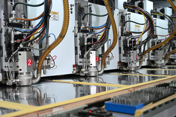
Rotating carbide tools cut plated and nonplated holes through copper, resin, and glass reinforcement. This is the standard process for through vias, component holes, tooling holes, and larger mounting holes.
Its main design constraint is aspect ratio, calculated as hole depth divided by the drilled or finished diameter according to the fabricator's rule. A deep, narrow hole is harder to clean and plate uniformly. Small tools also wear faster, and worn tools can cause burrs, resin smear, rough hole walls, or positional error. Designers should therefore confirm the minimum hole size together with board thickness and copper weight, not as an isolated capability.
What Is Laser Drilling
Controlled laser pulses remove material, usually to form blind microvias between adjacent layers in an HDI stackup. CO2 systems are widely used for resin removal, while UV systems can create smaller features and process copper and dielectric with finer control.
Because the process has no cutting tool, it avoids drill bit wear and can place very small holes at high speed. It is not a simple substitute for a full-depth drilled hole. Microvia depth must remain low relative to diameter, and fabrication may require copper opening, debris removal, sequential lamination, copper filling, and additional inspection. Poor energy control can leave residue, damage the capture pad, or produce excessive taper.
Laser Drilling vs Mechanical Drilling Comparison
The table summarizes the practical differences that usually decide the process.
| Factor | Mechanical Drilling | Laser Drilling |
|---|---|---|
| Best suited to | Through holes, PTH components, standard vias, mounting holes | Blind microvias, via in pad, fine pitch BGA escape, HDI |
| Typical geometry | Larger diameter and full board depth | Small diameter and shallow depth, commonly one dielectric layer |
| Main limits | Tool diameter, wear, runout, board thickness, PTH aspect ratio | Material absorption, taper, debris, capture pad, microvia aspect ratio |
| Common defects | Burrs, smear, breakout, tool marks, drill wander | Residue, overburn, copper damage, taper, incomplete ablation |
| Cost pattern | Usually lower for standard holes; tiny tools and many hits raise cost | Higher setup and HDI process cost; efficient when density prevents a larger board |
| Design impact | Needs enough pad and clearance for registration and annular ring | Enables smaller pads, shorter interconnects, and denser routing |
Cost should be evaluated at board level. Conventional drilling usually minimizes fabrication cost on standard boards. The laser process can still reduce total product cost when microvias shrink the PCB, eliminate layers, or make fine pitch routing manufacturable. Stacked microvias, multiple buildup cycles, filled vias, and tight inspection requirements add cost regardless of hole count.
When to Choose Each Drilling Process
Choose the mechanical process when the hole must pass through the complete board, accept a component lead, provide mechanical clearance, or use a diameter that fits the fabricator's standard process. It is usually the lowest risk choice for conventional prototypes and volume production.
Choose the laser process when a small blind connection is required for HDI, especially under fine-pitch BGAs or in via-in-pad routing. The stackup should define which layers each microvia connects. Avoid assuming that a smaller via is automatically better; pad size, dielectric thickness, copper filling, thermal cycling, and registration still determine reliability.
Before requesting a quote, provide the stackup, finished board thickness, drill and route files, finished hole sizes, plating status, hole tolerances, via structure, and whether microvias are staggered or stacked. Ask the fabricator to review aspect ratio, annular ring, drill-to-copper clearance, and microvia depth before release. This check prevents redesign after tooling starts.
PCBgogo Support for Both Drilling Methods
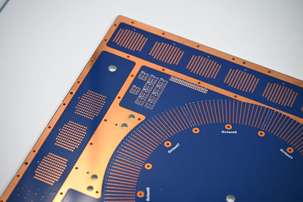
Boards that combine standard holes with HDI microvias benefit from one coordinated DFM review. PCBgogo supports conventional plated and nonplated holes, plus HDI constructions with blind microvias, stacked or staggered structures, via in pad, copper-filled microvias, and sequential lamination.
Published PCBgogo capability data lists minimum laser microvias of 0.10 mm for small and medium volume production and 0.075 mm for prototype work, while the practical mechanical drill limit depends on thickness and aspect ratio. These figures are capability limits, not automatic design targets. Submit the real stackup and production quantity so engineering can confirm the manufacturable combination and identify cost drivers before fabrication.
PCBgogo - Reliable, High-Quality PCB Manufacturing
PCBgogo is a one-stop PCB and PCBA manufacturing factory, helping you save time and costs while ensuring consistent, reliable quality.
Get a Free Quote >
Conclusion
In laser drilling vs mechanical drilling, geometry and function decide the winner. Use mechanical drilling for economical full depth and larger holes, use laser drilling for shallow HDI microvias, and combine both when the board needs density without forcing every connection into an advanced process.
Frequently Asked Questions
Can lasers make through holes in a multilayer PCB?
It is technically possible in limited constructions, but it is rarely the economical production choice for a conventional full-thickness board. Mechanical drilling remains the normal method for through holes, while laser drilling is optimized for shallow microvias.
Is laser drilling always more accurate than mechanical drilling?
Laser drilling can create smaller holes without tool wear, but final accuracy still depends on imaging, registration, material movement, energy control, and the stackup. Mechanical drilling is highly repeatable when hole size and aspect ratio stay within the process window.
Why are laser-drilled microvias usually blind?
A shallow blind microvia gives the laser a controlled dielectric thickness and keeps the depth-to-diameter ratio suitable for cleaning and plating. Reaching more layers normally requires sequential lamination or stacked microvias.
Can one PCB use laser drilling and mechanical drilling?
Yes. A common mixed design uses laser drilling for BGA escape microvias and mechanical drilling for through vias, component leads, and mounting holes. The drill files and fabrication drawing must distinguish each hole type clearly.





