
 日本語
日本語
 한국어
한국어

How to Use a Multimeter for PCB Testing Complete Guide
To use a multimeter on a PCB, choose the correct function, connect the black lead to COM, place the red lead in the proper input, and verify whether the circuit should be powered. Measure voltage in parallel on a live circuit. Measure resistance, continuity, and diodes only after power is removed and capacitors are discharged.
What a Multimeter Can and Cannot Diagnose
A multimeter helps diagnose PCB faults by measuring voltage, current, resistance, continuity, and semiconductor junction behavior at selected test points. It is often the fastest tool for determining whether power reaches the board, a fuse is open, a power rail is shorted, or a connector path is intact.
A digital multimeter typically measures voltage, current, and resistance. On a PCB, however, these readings are meaningful only when compared with the schematic, the expected operating state, and an appropriate reference point.
A multimeter can identify many static electrical faults, but it cannot fully reveal high-speed signals, intermittent glitches, waveform distortion, timing errors, or complex communication problems. These conditions may require an oscilloscope, logic analyzer, or dedicated diagnostic equipment.
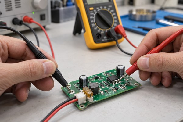
Multimeter Functions Used for PCB Testing
The useful multimeter function depends on whether the board is powered and whether the meter must be placed in parallel or in series. Selecting the wrong input jack can create a short even when the dial appears correct.
This table shows the common PCB measurements and the correct basic connection.
| Function | Board power | Meter connection | Typical PCB use |
|---|---|---|---|
| DC voltage | On | Parallel | Check input, regulator, and logic rails |
| Resistance | Off | Across isolated nodes | Compare resistor or rail resistance |
| Continuity | Off | Across a path | Check fuse, trace, cable, or connector |
| Diode test | Off | Across junction in both directions | Check diode, LED, or protection junction |
| Current | On | Series with opened circuit | Measure board or branch consumption |
The black lead normally stays in COM. The red lead uses the V and ohm input for voltage, resistance, continuity, and diode tests. Move it to the current input only for a series current measurement, then return it immediately after the test.
Safety Checks Before Probing a PCB
Safe PCB testing begins by identifying voltage, stored energy, isolation boundaries, and the meter rating before the probes touch copper. A low voltage battery board and an exposed mains power supply are not the same task.
Identify hazardous energy: Look for mains input, large capacitors, battery packs, motor buses, and high voltage labels. Beginners should not probe exposed mains circuitry.
Inspect the meter and leads: Check insulation, probe tips, input jacks, fuses, and voltage rating. A damaged lead can defeat an otherwise suitable meter.
Select the measurement first: Set the function and jack positions before contacting the board. Start on a higher manual range when the expected value is uncertain.
Remove power for passive tests: Disconnect all power sources and safely discharge capacitors before measuring resistance, continuity, or diode junctions. Never use these modes on an energized circuit.
Measurement-category ratings describe the transient environments a meter is designed to withstand. A high voltage rating alone does not make a meter suitable for mains or electrical-distribution work; both its voltage and category ratings must match the testing environment.
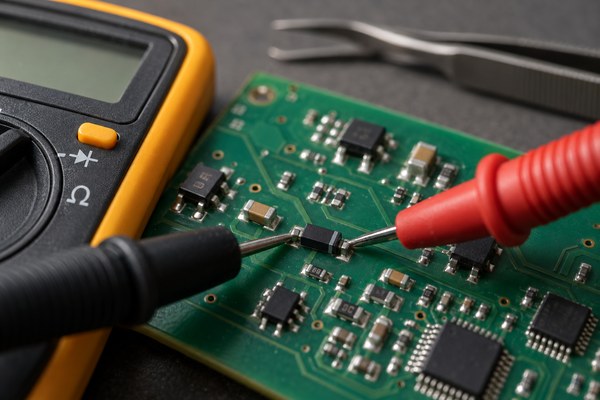
How to Measure Voltage on a PCB
Voltage measurement compares two powered nodes and places the multimeter in parallel with the circuit. For most low voltage PCBs, connect the black probe to the intended circuit ground and use the red probe to follow the power path.
Confirm the source: Measure the supply before connecting it to the board. Verify polarity and expected voltage.
Start at the input: Check voltage at the connector, then on both sides of the fuse, reverse polarity device, filter, and protection circuit.
Measure each regulator: Compare input, enable, and output pins with the schematic or datasheet. A correct input with zero output may indicate shutdown, protection, damage, or a shorted load.
Check voltage under load: A rail that looks normal with the circuit idle can collapse when a motor, radio, or processor starts. Record the operating state with each reading.
A current limited bench supply adds protection during first power up. Set the expected voltage and a conservative current limit before connecting the board, then watch both rail voltage and supply current for abnormal behavior.
How to Check Continuity Resistance and Diodes
Continuity, resistance, and diode modes apply a small test signal from the meter, so the PCB must be unpowered and fully discharged. In-circuit readings include every parallel path between the probes, which can make a functional component appear different from its marked value.
For continuity testing, touch the probes together first and note the lead resistance and beep response. Test from a connector pin to the next accessible circuit node rather than merely across the visible solder joint. Because the continuity threshold varies by meter and range, the displayed resistance is more informative than the audible beep alone.
For resistance measurements, disconnect or lift one component lead when parallel paths make the reading ambiguous. Ordinary test leads may add roughly 0.2–0.5 Ω to a low-resistance measurement. Use the meter’s relative function when available, or subtract the resistance measured with the probes shorted together.
In diode mode, compare the forward-voltage reading in both probe directions. Keep in mind that surrounding components and parallel current paths can affect in-circuit results. Remove or isolate the component when the reading remains inconclusive.
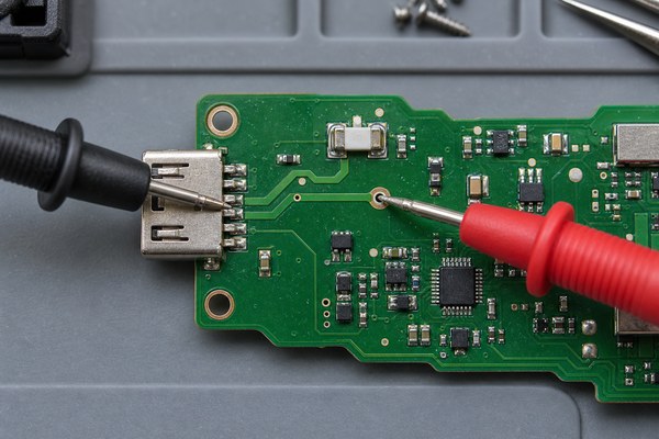
How to Measure Current Without Shorting the Supply
Current measurement requires the meter to become part of the current path. The circuit must be opened and the meter inserted in series. Connecting a meter in current mode directly across a supply creates a low-resistance path that can blow the meter fuse, damage the PCB, or cause a serious safety hazard.
Move the red probe to the correct fused current input and select the highest appropriate range. With power removed, open the branch at a connector, jumper, or removable link and insert the meter. Restore power and observe both startup and steady-state current.
Many handheld meters have a direct-current limit near 10 A, often with strict measurement-duration and cooling requirements. Always check the meter’s input rating, fuse specification, and time limit before testing.
During early debugging, a current-limited bench supply is often safer for monitoring total board consumption. Another option is to measure the voltage across a small shunt resistor and calculate the current using Ohm’s law. The shunt’s resistance, tolerance, power rating, and effect on circuit voltage must all be considered.
A Practical PCB Troubleshooting Sequence
A practical PCB troubleshooting sequence moves from visual evidence to power integrity, connectivity, components, and timed signals. Random probing creates many numbers but little diagnostic value.
No power: Inspect polarity and damage, verify the source, then measure voltage through the input protection path and each regulator.
Shorted rail: With power off, compare resistance to ground across rails. Use current limiting and isolate sections because low resistance is not automatically a fault on processor rails.
Broken trace: Use continuity to divide the path into smaller segments. Test through vias and connectors, where mechanical or plating faults commonly appear.
Poor solder joint: Look for intermittent continuity or voltage drop while applying controlled movement. Magnification and AOI may reveal cracks or insufficient wetting that a static meter check misses.
Communication failure: Confirm rail and reset levels with the meter, then move to an oscilloscope or logic analyzer for clocks, edges, protocol, and timing.
Frequently Asked Questions About Using a Multimeter
These questions address mistakes that commonly produce misleading readings or damaged meter fuses during PCB testing.
Can I test resistance while a PCB is powered?
No. Remove all power and discharge capacitors before resistance measurement. External voltage can corrupt the reading and may damage the meter.
Why does continuity beep between power and ground?
The meter beeps when measured resistance falls below its internal threshold. Capacitors, protection paths, and low resistance loads can trigger a beep, so watch the numeric reading and compare with the circuit design.
Why is an in circuit resistor reading too low?
Other components can create parallel paths that reduce the measured resistance. Lift one end of the resistor or compare the circuit with a known good board when the exact value matters.
When should I use an oscilloscope instead of a multimeter?
Use an oscilloscope when the problem involves ripple, startup timing, clocks, communication edges, pulses, or brief dropouts. A multimeter is best for steady levels and basic connectivity.
Conclusion
Knowing how to use a multimeter means matching the function, jack, circuit state, and connection method to the measurement. Start with safe power checks, use passive tests only on a discharged board, and move to waveform or production inspection tools when the fault is outside a meter's view.





