日本語
 한국어

How to Read an Engineering Drawing for CNC Machining
Quick Answer To read an engineering drawing for CNC machining, confirm the revision, units, material, and projection method first. Then reconstruct the part from its views, identify datums, read dimensions with their tolerances, decode feature controls and surface requirements, and convert every critical callout into a machining and inspection step.
Why engineering drawings matter in CNC machining
A 3D model shows nominal shape, while the engineering drawing defines the conditions that make a machined part acceptable. It records tolerances, geometric relationships, material, threads, surface texture, edge treatment, and inspection notes.
The safest method is to follow the same reading order every time. Reading a tight dimension before understanding its datum system can produce the wrong setup, while reading only the model can hide requirements that change the process and quote.
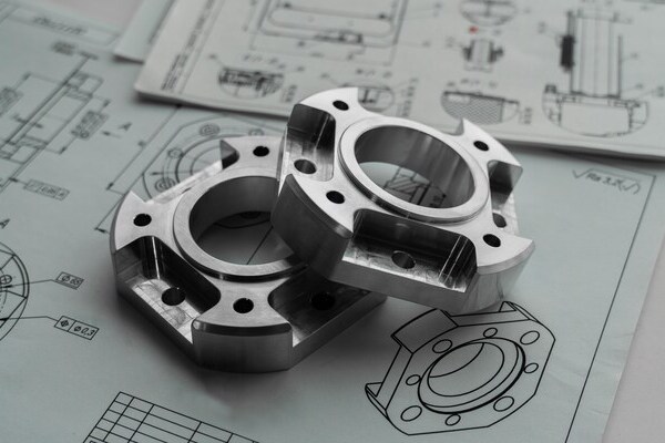
How to read an engineering drawing in eight steps
A repeatable reading sequence reduces assumptions and connects design intent to CNC operations.
1. Confirm document control: Check the part and drawing numbers, revision, approval status, and sheet count. Match the revision to the 3D model and order. If controlled files disagree, request clarification.
2. Read the title block. Confirm units, material, heat treatment, coating, scale, general tolerances, and drawing standard. ASME Y14.5 and ISO 1101 use standardized geometric tolerancing language. Follow the standard and edition listed on the drawing.
3. Check the projection method. Identify first angle or third angle projection before matching views. The top view normally sits above the front view in third angle projection and below it in first angle projection. Trust the projection symbol, not habit.
4. Reconstruct the geometry. Use outlines, hidden lines, centerlines, sections, details, and the isometric view to picture the part. Section arrows show viewing direction, and labels such as A A connect the cutting plane to its section. Never measure a feature from the printed page.
5. Trace dimensions feature by feature. Locate overall size, then holes, pockets, slots, steps, radii, chamfers, and threads. Read every value with its tolerance. Boxed basic dimensions are theoretically exact; a related feature control frame supplies the allowable variation.
6 Identify datums and geometric controls. Datums establish the reference frame for setup and measurement. A planar 3 2 1 scheme constrains three degrees of freedom with the primary datum, two with the secondary, and one with the tertiary. Read each feature control frame from left to right.
7 Read surface and edge requirements. A value such as Ra 3.2 micrometers controls roughness, not size or flatness. Check notes for deburring, edge breaks, corner radii, coating, and whether dimensions apply before or after finishing.
8. Turn requirements into a control plan. Mark every feature that affects setup, tooling, or inspection. Decide which datum surfaces come first, which relationships need one setup, and how each critical requirement will be verified.
Engineering drawing symbols that change CNC decisions
The most useful symbols are the ones that change tool selection, setup strategy, or measurement. This table links common callouts to their practical CNC meaning.
| Callout | What it controls | CNC implication |
|---|---|---|
| Diameter and radius | Cylindrical or arc size | Choose drilling, reaming, boring, or contouring from tolerance and finish. |
| Depth | Blind hole or pocket depth | Check tool reach, drill point allowance, bottom form, and clearance. |
| Thread callout | Form, size, pitch, class, and depth | Match the tap or thread mill and distinguish full thread from drilled depth. |
| Position | Feature location from datums | Align to the datum frame and plan CMM or functional gage inspection. |
| Flatness | Variation of one surface | Plan facing, stress control, and full area measurement. No datum is required. |
| Perpendicularity | Orientation to a datum | Machine related faces together when possible, then inspect from the datum. |
| Runout | Rotation about a datum axis | Control chucking, center alignment, finishing, and rotational inspection. |
| Surface texture | Microscopic irregularity | Choose feeds, tool geometry, finishing allowance, and roughness measurement. |
How dimensions and tolerances affect the CNC process
Dimensions define nominal size and location; tolerances define acceptable variation. Bilateral tolerance permits variation in both directions, unilateral tolerance favors one direction, and limit dimensions state maximum and minimum values. Programmers and inspectors must use the exact limits shown.
Title block rules may assign default tolerances by decimal places. Fit designations require the stated system: H7 is not one universal plus or minus value because its limits depend on nominal diameter and the referenced fit standard.
Tight requirements shape operation order. A bore with close size and position controls may need roughing and boring or reaming after datum faces are established. Completing related features without releasing the part reduces reclamping error.
How to read GD and T for machining and inspection
Geometric dimensioning and tolerancing defines allowable shape, orientation, and location. Read a feature control frame from left to right: characteristic, tolerance and zone shape, material condition modifier, then datum references in priority order.
Form controls: Straightness, flatness, circularity, and cylindricity control a feature itself and generally need no datum.
Orientation controls: Parallelism, perpendicularity, and angularity control a feature relative to datums.
Location controls: Position and profile locate a feature or surface within the datum frame.
Runout controls: Circular and total runout evaluate rotating surfaces relative to a datum axis.
At maximum material condition, a feature of size may gain bonus tolerance as it departs from its maximum material boundary. Calculate that allowance under the governing standard. If the symbol or datum logic is unclear, raise a formal drawing question.
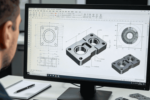
A practical CNC drawing review example
Consider a milled aluminum housing with datum A on the base, B on a long side, and C on an end. Four mounting holes have basic locations and position tolerance to A, B, and C. The top sealing face has a texture requirement.
Establish A first, then machine or qualify B and C so later work uses the same frame. Produce the hole pattern from those datums, not a raw edge. Leave finishing allowance on the sealing face, and reproduce the A B C alignment during inspection. This connects the drawing to fixturing, CAM coordinates, and measurement.
Common mistakes when reading CNC drawings
Most drawing errors come from skipping context or treating one callout in isolation.
Using an old revision: Verify the revision before quoting or programming. A conforming part to an obsolete drawing is still wrong.
Scaling the drawing: Exports and prints can be resized. Use stated dimensions, never a ruler on the page.
Ignoring general notes: Deburring, heat treatment, coating, inspection, and edge requirements may apply globally.
Confusing size with geometry: A hole can pass diameter and still fail position or perpendicularity.
Choosing a convenient work offset: The easiest clamping surface may not be the primary datum. Follow functional references where practical.
Assuming the model wins: Document any conflict and obtain an approved answer before cutting material.
CNC drawing review checklist
Before releasing a job, confirm that the following questions have clear answers.
Are the part number, revision, units, material, finish, and sheet count correct?
Is the projection method clear, and do all views describe the same geometry?
Which dimensions and geometric controls are critical to fit or function?
Which surfaces establish primary, secondary, and tertiary datums?
Can critical relationships be machined in one setup or with a controlled transfer?
Are thread, hole depth, radius, chamfer, edge, and surface texture callouts complete?
Can inspection measure each tolerance from the specified datum frame, and have all conflicts been resolved in writing?
Frequently asked questions
Should a CNC machinist read the drawing or the 3D model first
Read the drawing first to identify revision, material, tolerances, datums, and special requirements, then use the matching 3D model to understand geometry and create toolpaths. Neither file should silently override the other.
What is the difference between a datum and a dimension
A datum is a theoretically exact reference derived from a physical feature, while a dimension states size or location. Datums build the coordinate system used to interpret geometric tolerances and inspect the part.
Does a tighter tolerance always improve a CNC part
No. A tighter tolerance is useful only when function, fit, life, or interchangeability requires it. Unnecessary precision can add setups, finishing operations, inspection time, and scrap risk without improving performance.
How should an unclear engineering drawing be handled
List the exact conflict, affected feature, and proposed interpretation, then request written approval from the drawing owner. Record the answer with the job so programming, production, and inspection follow the same decision.
Read the drawing as a manufacturing plan
The best way to read an engineering drawing for CNC machining is to move from document control to geometry, then from tolerances to datums, process steps, and inspection. Before requesting a quote or releasing a program, provide a matched 3D model and controlled 2D drawing, highlight critical features, and resolve every ambiguity that could change how the part is made or accepted.