




 日本語
日本語
 한국어
한국어

How to Extend Bending Cycle Life of FPCB for Foldable Device Hinges
QUICK ANSWER A foldable hinge FPCB lasts longer when its dynamic bend zone uses fatigue-suitable copper, keeps conductors close to the neutral bend axis, avoids abrupt stiffness changes, and follows a measured hinge path. The final proof is an assembly-level bend test that reproduces the actual radius, motion, contact surfaces, and electrical load.
A foldable hinge FPCB is a moving electromechanical part, not just a cable that happens to be flexible. During every opening and closing event, the FPCB can see tension on one face, compression on the other, sliding against guides, and local distortion at retention features. If the mechanical team defines the hinge after the PCB layout is released, fatigue damage usually concentrates at one small, poorly controlled point.
The useful reliability question is where maximum strain occurs in the completed product, how it changes through motion, and whether copper, coverlay, adhesive, and the hinge guide remain protected. The workflow below connects these decisions before an open circuit reaches validation.
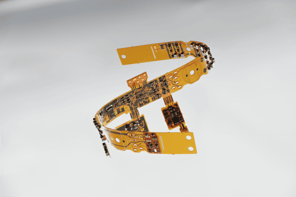
What Strain Tells You About Foldable Hinge FPCB Cycle Life
Bending strain is governed mainly by bend radius and by each conductor's distance from the neutral bend axis. A conductor farther from that axis experiences more cyclic strain, so a thin and balanced dynamic construction normally has more fatigue margin than a thick, asymmetric one. As a first screening model, strain rises as the distance from the neutral axis increases and as bend radius decreases.
This explains why a flex can pass a simple bench bend yet fail in a product hinge. A real assembly can introduce a moving radius, edge contact, torsion, or a clamp line, so calculations are an early filter and physical cycling is the final qualification.
The dynamic bend zone needs its own rules
A dynamic bend zone is the FPCB length that repeatedly changes curvature during hinge motion. Mark it in mechanical, layout, and fabrication documents, and allow only the features needed to carry signals through it.
No vias or plated holes: A via barrel, pad, or local plating feature is much less compliant than a plain trace and can become a crack initiation site.
No component lands or test pads: Move soldered features and probe targets outside the moving length, even if that requires a longer tail.
No stiffener termination at peak curvature: A sudden change from reinforced to free flex can force the cable to fold at the stiffener edge.
No coverlay opening in the bend: An opening exposes copper edges and creates a local construction discontinuity where the cable needs the most uniform support.
Material and routing choices then reduce remaining strain.
Choose an FPCB Stack Up That Resists Repeated Bending
A dynamic flex stack-up should minimize thickness while keeping copper placement predictable. Rolled annealed copper is the usual first choice for high cycle bending because it is better suited to repeated flexing than standard electrodeposited copper.
Use the fewest copper layers that the circuit can support. Where two layers are required, avoid dense trace groups directly above one another; staggered routing and a balanced construction reduce the chance of a stiff copper column shifting the neutral axis. Adhesiveless polyimide copper can reduce thickness and remove an adhesive interface, provided the electrical and manufacturing requirements are met.
Do not choose a thin stack-up by thickness alone. Current, impedance, voltage clearance, shielding, and connector transitions can require a more complex static area outside a thin moving zone.
The table below compares common stack-up choices for hinge work.
| Construction choice | Best fit in a foldable device | Cycle life consideration |
|---|---|---|
| Single layer FPCB | Signal tail with modest routing density | Lowest structural complexity and the easiest construction to bend repeatedly. |
| Two-layer FPCB | Higher signal count with careful routing | Keep traces staggered, avoid aligned copper density, and keep the dynamic zone balanced. |
| Rigid flex transition | Connector or component area outside the moving zone | Use the rigid portion for termination only; keep the repeated bend in the flexible tail. |
| Stiffened FPCB | ZIF connector or local support area | Terminate stiffeners well away from peak curvature and leave free flex for the transition. |
Route Conductors for Motion Instead of Minimum Length
Dynamic bend routing should distribute deformation rather than concentrate it at corners, pads, or copper edges. In most hinge layouts, traces cross broadly perpendicular to the hinge axis so bending spreads along the conductor.
Rounded trace direction changes: Use generous curves or curved corner treatment in the moving zone. A sharp 90-degree corner concentrates stress in the copper.
Even copper distribution: Avoid a wide solid copper patch beside a sparse signal region. A sudden stiffness difference can make the cable bend unevenly.
Controlled trace spacing: Keep spacing uniform enough that adjacent traces do not form a rigid band. Electrical isolation and manufacturing tolerances still set the minimum spacing.
Power path review: A wide power trace is mechanically stiffer. Check its current and temperature requirements, then place it close to the neutral axis or separate the architecture if needed.
No copper features at the bend boundary: Do not let a pad, neckdown, coverlay opening, or shield edge sit exactly where the hinge starts to curve.
These rules reduce internal stress, but they cannot compensate for a hinge that pinches or scuffs the flex. The mechanical path must now be checked with the same discipline.
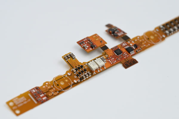
How the Hinge Interface Controls the Actual Bend Radius
The hinge interface determines the real bend radius because it guides, retains, and sometimes slides the FPCB. Define the rotation center, angles, guide radius, cable travel, retention points, clearance, and assembly tolerance. Inspect the cable open, closed, and at the position where curvature is smallest.
The FPCB needs enough support to follow the designed curve, but it must not be trapped. A guide edge that becomes a line contact under tolerance stack-up can cut the coverlay or impose a permanent crease. Review gaskets, shields, covers, and tapes after thermal aging because they can alter the cable path.
Stiffeners and shielding must stop before the moving section
Stiffeners and shielding films are useful only when their added rigidity stays outside the dynamic bend zone. FR4 or polyimide stiffeners support connectors, while shielding and adhesive features can solve EMI or retention needs, but none should extend to the location of repeated maximum curvature. Give the cable enough unsupported length to make a gradual transition from the reinforced area to the moving section.
This is also a practical point for procurement. PCBgogo offers flexible PCB constructions with polyimide materials, multiple layer options, stiffener choices, and EMI shielding film options. A fabrication review is most useful when the drawing explicitly separates those static support features from the high-cycle bend region, instead of leaving the manufacturer to infer the intended motion.
Fabrication Details That Preserve the Design Margin
Fabrication controls preserve cycle life by keeping defects out of the dynamic bend zone. The release package should identify copper type, finished thickness, coverlay system, bend boundaries, and excluded features so process concerns are flagged before production.
Coverlay registration and bond integrity matter as much as the nominal stack-up. A void, exposed copper edge, or displaced coverlay opening can become the first point of wear. Requires clean handling and protective packaging because a scratch or crease in an active bend length can become a fatigue origin.
Use this release table to turn the design intent into manufacturing evidence.
| Release item | What to specify or review | Useful evidence |
|---|---|---|
| Material callout | Copper type, polyimide and coverlay thickness, adhesive system, and finished stack-up tolerance. | Approved stack up and material record. |
| Controlled dynamic zone | Dimensioned area with exclusions for vias, pads, stiffeners, openings, tapes, and shields. | Fabrication drawing and CAM review comments. |
| Process robustness | Etch compensation, coverlay registration, handling method, and panel support for the selected construction. | DFM feedback before release. |
| Reliability sample | Coupon or cable made with the same critical materials and process steps as the production part. | Sample identification and lot traceability. |
| Incoming quality | Visual criteria, thickness checks, and electrical test coverage before hinge assembly. | Inspection and electrical test record. |
Validate the Complete Hinge with Dynamic Bend Testing
A representative dynamic bend test proves cycle life for a foldable hinge FPCB. A mandrel can compare materials, but it cannot reproduce a product's guide edge, migration, clamp force, or abrasion. Use the production hinge or an equivalent fixture with the same radius, routing, speed, dwell, preload, and contact surfaces.
Measure resistance before cycling and at defined intervals, and monitor continuity during motion when needed. Include product-relevant functional checks and inspect the cable edge, coverlay, stiffener transition, and guide surface for wear or drift.
Open circuit at one repeatable cycle count: Section the failure location and map the actual local radius. The correction is usually lower strain through stack-up, routing, or guidance, not a generic material substitution.
Intermittent signal only during motion: Log resistance while folding. Early copper microcracks can remain electrically invisible when the cable is held still.
Coverlay whitening or wear: Inspect guide contact, cable retention, and debris. This signature often indicates abrasion or pinching rather than intrinsic copper fatigue.
Failures beside a stiffener: Move the stiffness transition farther from the active curve and provide more free flex length.
Random sample-to-sample failures: Audit assembly positioning, hinge tolerance, lot traceability, and incoming inspection because inconsistent cable routing is likely involved.
A test that links the observed failure signature to a physical location gives the next design spin a focused, defensible change list.
What Should Be Checked Before Releasing a Foldable Hinge FPCB
A release review should confirm cable path, minimum radius, conductor placement, and the absence of rigid features inside the marked bend zone.
Before production, ensure tolerance cannot move the cable onto a sharp edge and define a bend test that uses the intended hinge motion.
Frequently Asked Questions About Foldable Hinge FPCB Reliability
What copper is best for a high-cycle foldable hinge FPCB
Rolled annealed copper is generally the preferred starting point for conductors that repeatedly cross a hinge because it has better flex fatigue behavior than standard electrodeposited copper. The final selection still needs to match finished thickness, current, impedance, and the fabricator's available stack-ups.
Can a multilayer FPCB be used in a foldable device hinge
Yes, but each added layer increases thickness and can move conductors farther from the neutral bend axis. Keep the actual dynamic region as thin and balanced as possible, and stagger traces rather than aligning dense copper patterns through the bend.
Should vias be allowed in the dynamic bend zone?
No, vias and plated holes should be moved out of a high-cycle bend zone whenever possible. Their local rigidity and geometry make them poor candidates for a region that sees repeated curvature.
How do you choose the test cycle count for a foldable hinge FPCB
Choose it from the product use case, then test the complete hinge through the intended motion and relevant environmental conditions. The target should include a defined pass criterion for resistance, continuity during movement, functional performance, and visual condition.
Why does an FPCB fail beside a connector stiffener
The stiffener changes bending stiffness abruptly and can force the flex to fold at its edge. Move the transition away from peak curvature and provide enough free flex length for a gradual change in shape.
Conclusion
Long bending cycle life comes from treating the foldable hinge FPCB as a controlled mechanical and electrical system. A thin fatigue-suitable stack-up, motion-aware routing, a measured hinge path, disciplined fabrication controls, and representative dynamic testing work together to prevent the failures that a material choice alone cannot solve. For production planning, involve the FPCB manufacturer while the hinge path and controlled bend zone can still be changed.





