
 日本語
日本語
 한국어
한국어

How to Convert CAD Files to CNC-Machined Parts?
QUICK ANSWER
CAD to CNC is the controlled process of turning a 2D drawing or 3D model into a machined part. The design is checked for manufacturability, imported into CAM software, converted into toolpaths, post-processed into machine-specific G-code, simulated, proved out, machined, and inspected. A CAD file alone is not a safe machine program.
A clean model can still produce a bad part if units change, a cutter cannot reach a pocket, or the wrong post processor sends an unsafe command. A dependable CAD to CNC workflow therefore connects geometry, manufacturing intent, machine limits, and inspection.
This guide explains the complete handoff, the best file formats, what a CAD to CNC converter can and cannot do, and how to prepare a package that a machinist can quote and manufacture with fewer questions.
What Is CAD to CNC Workflow?
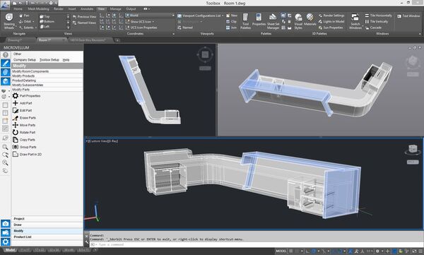
The CAD to CNC workflow is a digital chain in which CAD defines the part, CAM defines how material will be removed, and the CNC controller executes machine-specific instructions. Each stage adds information that the stage before it does not contain.
CAD: Computer-aided design stores nominal geometry such as faces, holes, pockets, and threads. A production model should be a closed solid with the correct units and revision.
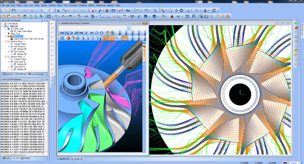
CAM: Computer-aided manufacturing assigns stock, workholding, tools, cutting operations, speeds, and feeds. It produces a toolpath, not a universally safe machine program.
Post processing: A post processor translates toolpath data into the syntax expected by a particular controller. Autodesk states that post processing outputs an NC file, usually G-code, and requires a post configuration suitable for the target machine.
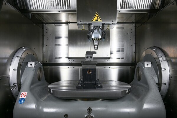
CNC execution: The controller interprets the NC program while the operator establishes work offsets, loads tools, verifies clearance, runs a safe prove-out, and checks the finished part.
The CAD to CAM to CNC workflow is more than a simple file conversion; it is a controlled engineering process that requires validation at every stage.
Common CAD Software for CNC Machining
The best CAD software for CNC machining depends on the part geometry, production complexity, budget, and whether CAM tools need to be integrated into the same platform. Regardless of the software used, the final model should have correct units, closed solid geometry, and clearly defined manufacturing features.
Autodesk Fusion: A practical option for individual designers, startups, and machine shops because it combines parametric CAD, CAM, simulation, and post-processing in one platform. Its integrated workflow reduces file conversion and revision control problems.
SOLIDWORKS: Widely used for mechanical parts, assemblies, production drawings, and parametric product design. SOLIDWORKS CAM can create machining operations within the CAD environment and update them when the design changes.
AutoCAD: Best suited to 2D drawings, profiles, panels, signs, and basic mechanical layouts. AutoCAD designs are commonly exported as DXF files before toolpaths are created in separate CAM software.
Autodesk Inventor: Suitable for mechanical engineering, assemblies, tooling, and production equipment. Inventor models can be transferred to compatible CAM systems through native files or neutral formats such as STEP.
FreeCAD: An open source option for parametric 3D modeling and simpler CNC projects. It is useful for learners and budget-conscious users, although complex production work may require additional CAM tools and post processor validation.
Siemens NX: Designed for advanced industrial workflows involving complex assemblies, multi-axis machining, molds, aerospace components, and tightly controlled production processes.
The CNC supplier does not usually need the original CAD software. For most 3D machining projects, exporting a STEP file and attaching a dimensioned PDF drawing provides a reliable handoff. DXF is generally more appropriate for 2D cutting, while STL should be avoided when accurate solid geometry is required.
The CAD to CNC Process in Seven Practical Steps
A reliable CAD to CNC process uses seven steps, beginning with manufacturable geometry and ending with measured evidence that the part meets the drawing.
Model for machining. Use realistic internal corner radii, accessible tool directions, practical hole depths, and clampable stock. Deep narrow cavities and thin unsupported walls increase deflection, setup count, cycle time, and cost.
Confirm units and scale. Record millimeters or inches, then verify one known dimension after export. A unit mismatch can change scale by a factor of 25.4, so check every file handoff.
Export usable geometry. For 3D milling and turning, STEP is usually the strongest neutral starting point. NIST identifies STEP as ISO 10303 and notes that it supports exchange among CAD, CAM, analysis, and inspection systems. Use DXF for true 2D profiles.
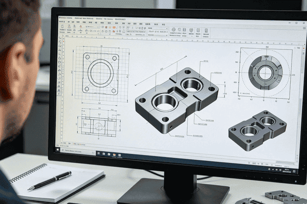
Attach manufacturing requirements. A 3D model rarely communicates every acceptance criterion. Add a controlled drawing for critical dimensions, tolerances, datums, threads, roughness, material, finish, quantity, and inspection needs. Tighten only dimensions that affect function.
Build and simulate the CAM setup. Define stock, orientation, coordinates, fixtures, tool holders, and operations. Simulate the setup to find collisions, unsafe rapid moves, remaining material, and unreachable features before cutting.
Post for the actual controller. Select a validated post processor for the exact machine and control. Autodesk warns that machines do not all use the same code syntax. Review tool changes, spindle direction, work offsets, coolant calls, safe heights, and units.
Prove out, machine, and inspect. Run a controlled first article with overrides and clearance checks. Inspect critical features, record deviations, and correct offsets, CAM, or the model before releasing the batch.
Which File Format Should You Use for CAD to CNC?
The best CAD to CNC format depends on whether the job is 3D machining, 2D profile cutting, collaboration within one software system, or mesh-based reference work.
| Format | Best use | Strength | Watch for |
|---|---|---|---|
| STEP | 3D milling and turning | Solid geometry and broad interoperability | Check imported units, faces, and revision |
| Native CAD | Same software ecosystem | May retain features and parameters | Version and license compatibility |
| DXF | 2D profiles and engraving | Simple curves and contours | Layers, duplicates, open loops, and units |
| IGES | Legacy 3D exchange | Broad older system support | Surface gaps and repair work |
| STL | Mesh reference | Easy to view | Facets, no true analytic faces, limited editability |
For most supplier handoffs, pair a STEP model with a PDF drawing. The model supplies CAM geometry, while the drawing defines acceptance criteria.
Can a CAD to CNC Converter Generate Ready to Run G-code?
A CAD to CNC converter can automate toolpath creation, but it cannot remove the need for machine-specific setup and verification. The phrase usually describes CAM software, an integrated platform, or an online quoting system, not a universal converter.
Geometry is not strategy: The model does not choose the best stock orientation, fixture, cutter length, roughing method, finishing allowance, or inspection sequence.
G-code is controller specific: A toolpath must be posted for the intended machine. Commands for tool changes, coolant, probing, work offsets, and rotary axes can differ between controls.
Automation needs boundaries: Feature recognition accelerates common holes and pockets, but delicate walls, undercuts, and multi-axis motion still need review.
Simulation is necessary but incomplete: CAM simulation checks the programmed virtual setup. It cannot confirm that the real vise, tool length, stock position, or offset matches the digital setup.
Use conversion software to reduce repetitive work, then keep a human approval gate before the program reaches the machine.
Common CAD to CNC Errors and How to Prevent Them
Most CAD to CNC failures come from missing requirements, inconsistent setup, or an unchecked assumption at the machine.
Open or damaged geometry: Repair gaps, self-intersections, duplicate contours, and nonmanifold bodies before CAM. Reopen the exported file in a neutral viewer to confirm the transfer.
Ambiguous tolerances: Identify critical fits and datums on a drawing. Default tolerances can make inspection unclear, while over-tolerancing raises cost without improving function.
Wrong work origin: Make the CAM coordinate system match the setup sheet and physical work offset. A correct toolpath referenced from the wrong zero can still crash or scrap the part.
Unreachable features: Check tool diameter, flute length, holder clearance, travel, and setup count. Redesigning a deep pocket may be cheaper than forcing an impractical cut.
Revision drift: Put the revision on the model, drawing, quote, and inspection report. Send one controlled package so production does not mix an old drawing with a new solid model.
A preflight checklist catches these issues early and gives the manufacturer enough information for useful DFM feedback.
How PCBgogo Applies CNC Control to PCB Manufacturing
A finished CAD model does not always mean a part is ready for production. Designers may still need to resolve file compatibility, inaccessible features, unrealistic tolerances, material selection, workholding, tool access, and surface finish requirements. PCBgogo’s standalone CNC machining service helps bridge these gaps and move projects from digital design to finished parts.
Instead of asking customers to prepare machine-specific G-code, PCBgogo can manage the manufacturing stages that follow the CAD model:
CAD file and DFM review: Engineers review the submitted model for machining risks such as deep cavities, sharp internal corners, thin walls, small features, and restricted tool access. Addressing these issues before production helps prevent unnecessary setups, delays, and part failures.
Tolerance and material guidance: The team evaluates whether the requested tolerances match the part’s function and selected material. This helps customers avoid paying for excessive precision while protecting critical fits, mating surfaces, and assembly requirements.
Production-ready CAM planning: Once the design is approved, the model is converted into machining operations, toolpaths, workholding strategies, and machine-specific instructions. Customers do not need to operate a CAD to CNC converter or create their own production G-code.
Prototype and batch production support: The same workflow can support early design validation, functional prototypes, low-volume orders, and repeat production. This allows design changes to be reviewed before larger quantities are manufactured.
Clear manufacturing communication: A complete production package connects the 3D model with the drawing, material, finish, quantity, and inspection requirements. Keeping these details together reduces revision errors and helps the finished parts match the original design intent.
If you already have a STEP, STP, IGES, or other 3D CAD file, attach a dimensioned drawing that identifies the material, critical tolerances, threads, surface finish, and required quantity. Send your CAD files to PCBgogo to discuss manufacturability and move your design toward CNC production.
Frequently Asked Questions About CAD to CNC
What is the CAD to CNC workflow in simple terms?
It is the process of creating part geometry in CAD, planning machining operations in CAM, posting machine-compatible G-code, and running the verified program on a CNC machine. Inspection closes the loop by confirming that the physical part meets the defined requirements.
What is the difference between CAD, CAM, and CNC?
CAD describes what the part should be, CAM describes how tools should make it, and CNC is the machine control system that executes the posted instructions. Confusing these roles is why a CAD model cannot normally be sent straight to a machine.
Is STEP better than STL for CNC machining?
STEP is usually better for precision CNC machining because it transfers solid and surface geometry instead of approximating the part with triangles. STL can work as a reference, but faceting and limited editability make it less suitable for accurate feature-based CAM.
Do I need to create G-code before sending a part to a supplier?
Usually no. A machining supplier normally wants the 3D model, a drawing, material, finish, quantity, and inspection requirements, then creates and validates CAM for its own machines. Sending unrequested G-code can add risk because it may not match the supplier's controller, tooling, or fixtures.
What should I upload for an accurate CNC quote?
Upload a STEP file and a revision-matched drawing, then specify material grade, finish, quantity, critical tolerances, threads, inserts, and inspection documentation. Mention mating parts or functional surfaces when they explain why a dimension matters.
From Digital Model to Measured Part
A successful CAD to CNC workflow is a verified engineering chain, not a one-click export. Build manufacturable geometry, transfer it in the right format, document the critical requirements, validate CAM and the post processor, prove out safely, and inspect the result before scaling production.





