



 日本語
日本語
 한국어
한국어

Heat Sink for PCB: Types, Attachment Methods & Selection Guide
When a PCB runs hot, components fail early. A heat sink is one of the simplest, most cost-effective fixes — a thermally conductive metal structure that absorbs heat from a component and dissipates it into the surrounding air. Choosing the right heat sink for your PCB, and attaching it correctly, can mean the difference between a reliable product and an expensive warranty problem.
What Is a PCB Heat Sink?
A PCB heat sink is a passive cooler — typically aluminum or copper — attached to high-power components such as processors, MOSFETs, and voltage regulators. It works through conduction: heat flows from the hot component into the heat sink's low-resistance metal body, then spreads across the fin surface and transfers to the air by convection.
The key performance metric is thermal resistance (°C/W). The lower the value, the more heat the sink removes per degree of temperature rise. A quality thermal interface material (TIM) — paste, phase-change pad, or graphite sheet — between the component and the heat sink is essential to eliminate air gaps that would otherwise act as insulators.
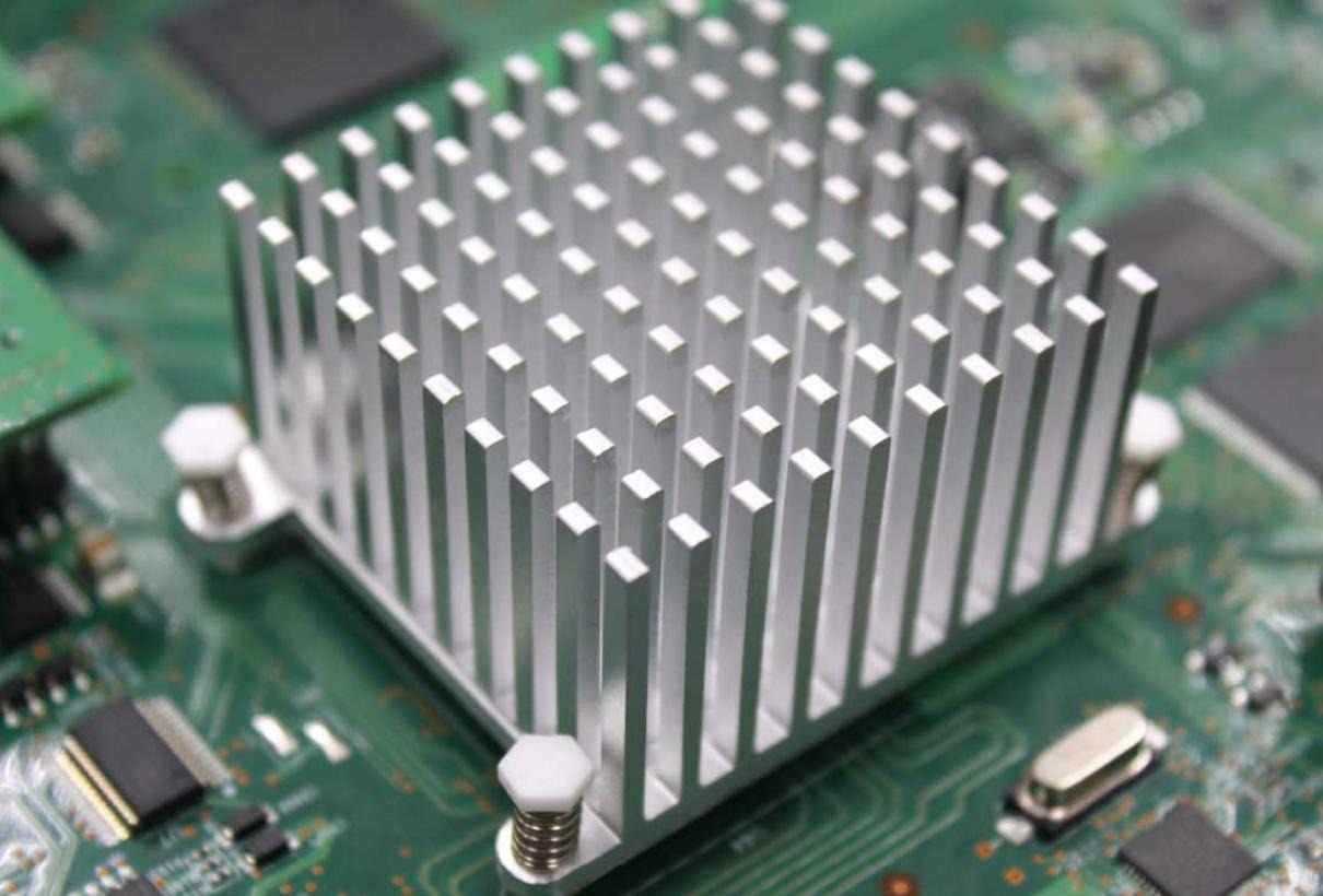
Common Types of Heat Sinks for PCB
Stamped: Punched from thin aluminum sheet. Lightweight, inexpensive, suitable for low-power components (< 5 W) such as small regulators and microcontrollers.
Extruded: Aluminum forced through a die to create finned profiles. Excellent performance-to-cost ratio; the standard choice for power supplies, motor drivers, and RF amplifiers (10–100 W).
Bonded Fin: Thin fins bonded to a base plate for maximum fin density. Used in base stations, inverters, and industrial controls where high heat loads meet restricted space.
Pin Fin: Array of cylindrical pins; performs equally in all airflow directions. Ideal for turbulent airflow environments — servers, graphics cards, telecom hardware.
Clip-On (Board-Level): Attaches to component packages directly via spring clips. No PCB modification required; easy to install and remove. Common in consumer electronics and LED driver boards.
Heat Sink Attachment Methods
How you attach a heat sink matters as much as which type you choose. Each attachment method offers a different balance of thermal performance, permanence, and assembly complexity.
Thermal Tape
Peel-and-stick pressure-sensitive tape with thermally conductive filler. Thermal conductivity: 0.8–1.5 W/m·K. Best for lightweight heat sinks on SMD components under 5 W. Fast to assemble and non-destructive to remove, but not suited for high-power or high-vibration applications.
Thermal Adhesive (Epoxy / Silicone)
A permanently bonding compound that outperforms tape thermally (1.5–3.0 W/m·K) and provides strong mechanical retention. Ideal for 10–30 W applications where rework is not expected. The main drawback: removing the heat sink risks damaging the PCB or component.
Z-Clips
Metal spring clips that anchor to the PCB and hold the heat sink in firm contact without adhesive. Used with a TIM for effective conductivity of 3.0–5.0 W/m·K. Fully reversible — ideal for applications of 20–50 W that may need servicing. Requires mounting anchor points to be designed into the PCB layout.
Push Pins
Spring-loaded pins pass through pre-drilled PCB holes and clip below the board, providing consistent clamping force. Effective conductivity of 3.0–5.0 W/m·K via TIM. Fast to install and remove — the standard choice for high-power CPUs, power transistors, and server components (50–100 W). Requires 2.5–4.0 mm holes planned into the layout.
Attachment Method Quick Reference
| Method | Conductivity (W/m·K) | Power Range | Reversible? | PCB Modification? |
|---|---|---|---|---|
| Thermal Tape | 0.8–1.5 | < 5 W | Partial | None |
| Thermal Adhesive | 1.5–3.0 | 10–30 W | No | None |
| Z-Clips | 3.0–5.0* | 20–50 W | Yes | Anchor points |
| Push Pins | 3.0–5.0* | 50–100 W | Yes | Drilled holes |
* Via thermal interface material (TIM).
How to Choose the Right Heat Sink for Your PCB
Calculate thermal requirements first: Determine the component's thermal design power (TDP) and maximum allowable junction temperature. Required thermal resistance = ΔT ÷ P.
Match power range to attachment method: Use the table above as a starting point. High-power components (50 W+) need mechanical attachment with TIM — tape will not suffice.
Consider serviceability: If the board will ever be reworked or components replaced, avoid permanent adhesive. Z-clips and push pins are the better choice.
Plan the PCB layout early: Mechanical attachments (Z-clips, push pins) require holes or anchor features. Design these in before routing — retrofitting is costly.
Always use a TIM: Even with a mechanically attached heat sink, a quality TIM is non-negotiable. Dry metal-to-metal contact leaves air gaps that dramatically increase thermal resistance.
Conclusion
A heat sink for PCB is a straightforward solution to a common problem, but only when the type, material, and attachment method are correctly matched to the application. Stamped and clip-on designs handle lightweight, low-power jobs efficiently. Extruded and bonded fin sinks scale to demanding industrial and telecom loads. Thermal tape works for quick, low-power assembly; push pins and Z-clips provide the performance and reversibility that high-power designs require.
Start with your thermal requirements, plan mounting features into the PCB layout early, always pair any attachment with a quality TIM, and validate with testing before production. Get these steps right, and your components will run cooler, last longer, and perform reliably throughout the product's service life.





