



 日本語
日本語
 한국어
한국어

HDI PCB Design for Compact IoT Device Practical Guide
QUICK ANSWER For a reliable HDI PCB design for a compact IoT device, lock the enclosure, antenna, BGA fanout, power peaks, and fabrication limits before placement. Use the simplest HDI build that clears routing, keep RF and return paths continuous, verify power under radio bursts, and send the fabricator a complete stackup and drill definition.
A compact IoT board can look generous in the schematic and become crowded the moment the enclosure, antenna keepout, battery connector, sensors, and programming access are placed. The purpose of HDI PCB design for compact IoT devices is to create routing room without weakening return paths or adding fabrication steps that the product does not need.
This guide follows an anonymized PCBgogo manufacturing case and gives designers measurable review points for the next HDI PCB design for a compact IoT device project.

A PCBgogo HDI Application Case for an IoT Asset Tracker
This HDI PCB design for a compact IoT device case concerns a battery-powered asset tracker on a 42 mm by 30 mm rigid board manufactured by PCBgogo. It combines a 0.5 mm pitch BGA processor, two radios, motion and temperature sensing, USB, battery charging, and 1.8 V plus 3.3 V rails.
The enclosure fixed the outline, antenna edges, mounting holes, USB opening, and a 2.4 mm component height limit. Escape routing showed that through vias consumed the inner BGA channels, so the build used a six layer 1+4+1 stackup, 0.10 mm laser microvias, selective filled via in pad, controlled impedance RF traces, and high Tg FR 4.
The table records the design inputs that drove the HDI PCB design for the compact IoT device decision. Values are project requirements, not universal rules.
| Input | Project value | Why it mattered |
|---|---|---|
| Board envelope | 42 mm by 30 mm | No room to enlarge the outline or move connectors |
| Dense package | 0.5 mm pitch BGA | Inner rows needed laser microvia escape |
| Radio paths | 2.4 GHz and sub-GHz | Required controlled geometry and clear antenna regions |
| Power event | Short radio transmit bursts | Forced low-inductance decoupling and rail validation |
| HDI build | Six-layer 1+4+1 | One build-up layer per side solved escape without stacked vias |
The build used HDI only where density required it because each extra lamination cycle adds cost and registration risk.
Design Challenges That Had to Be Solved Before Routing
The main challenge in HDI PCB design for a compact IoT device is that mechanical, electrical, RF, and manufacturing constraints occupy the same small area. Four issues were locked before detailed placement.
BGA escape: The 0.5 mm pitch device could not use dogbone fanout for every row. Microvias served blocked inner rows, while outer rows escaped on the surface.
Antenna coexistence: The radios needed edge locations, all-layer copper keepouts, and separation from switch nodes, clocks, USB, and the battery lead.
Burst current: Planes, vias, and local capacitance were sized for radio transmit, with droop checked at the device pins.
Assembly access: Test pads, programming contacts, fiducials, and connector joints were fixed before routing.
Why HDI Was the Right Choice
HDI was justified because it removed a specific breakout bottleneck that a conventional via structure could not clear. In this compact IoT device, simply adding two conventional layers would not recover the routing area lost to large capture pads and through holes beneath the BGA.
IPC-2226A treats microvias as high-density structures and provides a design framework for their geometry. PCBgogo lists 0.10 mm laser microvias for production, 0.075 mm microvias for engineering-reviewed prototypes, and common 1+N+1 through 3+N+3 constructions. The project stayed at 1+4+1 with adjacent-layer microvias because the routing did not require stacked structures.
HDI also shortened selected layer transitions and removed unused via stubs from the RF path. It did not replace disciplined placement, continuous reference planes, or impedance control. A compact IoT device should use a conventional PCB when a standard four- or six-layer board routes cleanly with adequate plane continuity and assembly access.
PCB Design Principles for a Buildable HDI Layout
A buildable HDI PCB design for a compact IoT device uses the least complex via strategy that completes the routing while preserving fabrication margin. The following rules controlled this project.
Freeze the stackup first: Obtain a reviewed dielectric and copper construction before calculating impedance or routing the BGA. A trace width based on an assumed dielectric does not constitute a controlled-impedance design.
Use microvias selectively: Place laser microvias on inner BGA rows and true density points. Keep through vias where their pad size causes no conflict.
Keep microvias shallow: PCBgogo specifies a 1:1 production depth-to-diameter ratio for microvias. With a 0.10 mm via, the finished build-up dielectric should therefore be no thicker than 0.10 mm unless the structure receives engineering review.
Protect return paths: A signal that changes layers needs a nearby ground transition. Never route a critical trace across a plane split, slot, or void created by a dense antipad field.
Prefer staggered structures: When two build-up layers are necessary, use staggered microvias unless the fabricator accepts the filling, plating, registration, and reliability plan for stacked structures.
PCB Materials and Manufacturing Process Choices
Material selection for HDI PCB design for a compact IoT device should reflect operating temperature, RF loss, board thickness, and lamination requirements instead of defaulting to an exotic laminate. The tracker used high-Tg FR-4 because its RF traces were short and the approved impedance geometry met the loss budget.
The outer build-up dielectric had to support laser ablation, reliable resin removal, copper adhesion, and the chosen microvia aspect ratio. Copper weight remained moderate on routing layers because heavy copper makes fine lines, small clearances, and uniform microvia plating more difficult. ENIG provided a flat surface for the fine-pitch BGA and small passive-component pads.
The table shows how common material and process choices affect an HDI PCB for a compact IoT device. Final values must be confirmed in the fabricator-approved stackup.
| Decision | Preferred starting point | Escalate when |
|---|---|---|
| Core and prepreg | High Tg FR 4 | Loss model or operating temperature fails the product budget |
| HDI structure | 1+N+1 adjacent layer vias | Escape study proves another build-up layer is necessary |
| Via arrangement | Staggered where possible | Area cannot support stagger and stacked vias pass review |
| Surface finish | ENIG for flat SMT lands | Wire bonding, contact wear, or another assembly process needs a different finish |
| Impedance | Coupon-based controlled build | Tighter tolerance is required by simulation or module guidance |
PCB Component Placement That Reduces Routing Pressure
Placement determines whether HDI PCB design for a compact IoT device remains a simple 1+N+1 build or requires costly additional lamination cycles. Place mechanically fixed and RF-sensitive parts first, then organize the remaining components around signal and current flow.
Lock antennas and connectors: Enforce antenna keepouts on all relevant layers and fix enclosure openings before optimizing density.
Place the BGA for escape: Provide routing channels on more than one side and rotate the package to reduce crossed interfaces.
Build the power path: Keep each regulator current loop compact and its switch copper away from RF, crystals, and sensor nodes.
Place decoupling by connection length: Connect each capacitor to power and ground pins through a short path, using direct microvias only where geometry requires them.
Reserve inspection and test access: Add fiducials, programming pads, rail test points, and probe clearance before filling remaining space.
Power Integrity Signal Integrity and RF Verification
Verification of HDI PCB design for a compact IoT device must test the assembled electrical behavior that the layout is intended to protect. Passing ERC and DRC confirms connectivity and rule compliance, not power-rail stability, return-path continuity, or antenna performance.
Power integrity: Include radio burst load, capacitor bias derating, plane resistance, and via inductance. Probe at the device pins and compare the minimum rail voltage with its operating limit plus margin.
Signal integrity: Check controlled nets against the released stackup, including reference changes, stubs, test pads, and return vias. Request TDR coupon results.
RF path: Route the 50 ohm feed over uninterrupted ground, preserve matching component order, avoid branches, and stitch ground without violating antenna keepout.
Pre-compliance: Test each radio mode during digital activity and battery charging. Radiated scans, antenna return loss, and receiver sensitivity reveal coupling that bare-board inspection cannot detect.
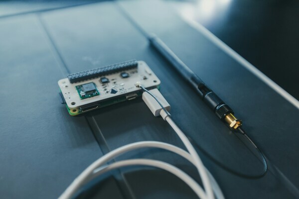
For this compact IoT device, the release review included power-rail waveforms during transmission, impedance-coupon requirements, RF-net geometry, antenna clearance, and return-path inspection at every layer transition. This evidence tied each verification result to the actual layout.
Design for Manufacturing Preparation
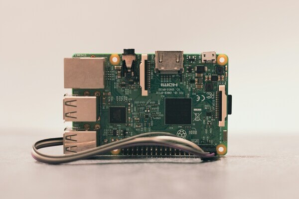
DFM preparation converts HDI PCB design data for a compact IoT device into an unambiguous fabrication and assembly package. PCBgogo can review laser drilling, sequential lamination, filled via-in-pad structures, controlled impedance, and registration, but the designer must state where each requirement applies.
Release the following files and notes together:
Fabrication data: Gerber X2 or ODB plus NC drill files separated by hole type and layer pair.
Approved stackup: Layer order, copper weights, dielectric thicknesses, finished thickness, material family, Tg requirement, and impedance structures.
Via table: Start and stop layers, finished diameter, pad diameter, fill type, cap plating, and whether any vias are stacked.
Impedance table: Net class, target impedance, tolerance, layer, reference plane, nominal width, and differential spacing where applicable.
Assembly package: Centroid data, BOM, polarity drawings, stencil notes, panel constraints, and inspection criteria.
Test requirements: Electrical test, impedance coupons, microsection or thermal reliability requirements, and any product-specific acceptance limits.
Before ordering, compare every rule in the CAD database with the current PCBgogo capability review. PCBgogo publishes 0.10 mm production microvias, 2.5 mil line and space capability, and controlled impedance with a standard tolerance of plus or minus 10 percent, with tighter prototype control subject to review. Treat those figures as a review starting point, not permission to combine every minimum on the same feature.
Summary
Successful HDI PCB design for a compact IoT device starts with fixed product constraints, demonstrates why HDI is needed, and uses the simplest reviewed structure that solves the breakout problem. A compact board becomes production-ready when placement, stackup, microvia geometry, PI, SI, RF, test access, and release data express the same manufacturing intent.
Send PCBgogo the preliminary stackup, BGA fanout, RF geometry, and via table before final routing so the design can be checked against the intended production process.
Frequently Asked Questions
When does a compact IoT product actually need HDI?
A compact product needs HDI when a documented escape study shows that standard through vias cannot route a fine-pitch package without compromising plane continuity, RF clearance, or assembly access. If a conventional four- or six-layer layout routes successfully with sound return paths, HDI may add cost without adding value.
Is a 1 plus N plus 1 stackup enough for a compact IoT device?
A 1+N+1 stackup is often the best starting point for HDI PCB design for a compact IoT device because it provides one microvia build-up layer on each side with only one sequential lamination stage. Confirm the structure through an escape study and a fabricator review rather than selecting it from package pitch alone.
What microvia aspect ratio should designers use?
Use the fabricator-approved ratio for the chosen dielectric and via process. PCBgogo lists 1:1 for production microvias and up to 1.2:1 for engineering-reviewed prototypes, so a 0.10 mm production microvia should not be assigned an unreviewed dielectric depth greater than 0.10 mm.
Does every BGA pad need a via in pad?
No. Use a via in pad only where the fanout requires it, because filling, planarization, and cap plating add process steps. Surface escape for outer rows and selectively filled microvias for blocked inner rows often give a better cost and yield balance.
How should a designer control HDI PCB cost?
Control cost by minimizing lamination cycles, avoiding stacked microvias unless proven necessary, using standard materials where the loss budget permits, and keeping minimum geometry local. Early placement and fanout studies usually save more than late attempts to simplify an already routed board.
What should be verified before the first prototype order?
Verify the approved stackup, microvia depth and fill, BGA fanout, copper balance, impedance table, antenna keepout, rail behavior under transmit load, test access, and drill layer pairs. Then run CAD DRC against the fabricator rules and obtain an HDI DFM review before release.





