



 日本語
日本語
 한국어
한국어

DIY Electronics: A Complete Technical Guide to Building Your Own Circuits
Building your first DIY electronics project can feel simple — connect a few components, upload some code, and watch it come to life. But what happens when the LED doesn’t light up, the sensor gives unexpected readings, or your circuit works once but fails the next time?
Successful electronics projects are built on understanding the fundamentals behind the wiring, not just copying a diagram. This guide covers the essential concepts, components, tools, and prototyping methods you need to troubleshoot problems, design better circuits, and move from simple experiments to reliable DIY electronics projects. It will help you build a stronger foundation in electronics, avoid common mistakes, and confidently turn your ideas into working circuits.
What DIY Electronics Actually Involves
DIY electronics covers any project where you design, wire, or program a circuit yourself rather than buying a finished device. That spans a huge range of complexity: a single LED wired to a coin cell, a microcontroller reading a temperature sensor and logging data, or a custom PCB running a battery management system. What ties all of it together isn't the specific project — it's a repeatable process: understand what the circuit needs to do electrically, select components that meet those electrical requirements, build a working prototype, and verify it behaves the way the math predicted.
Most guides on this topic default to a list of project ideas or a single tool (a specific connector, a specific board). That's useful once you already know what you're doing, but it skips the part that actually determines whether your next ten projects go smoothly: the fundamentals underneath the wiring.
The Four Fundamentals: Voltage, Current, Resistance, and Power
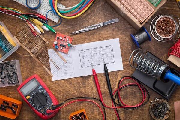
Every circuit, no matter how complex, is governed by the same four quantities and the relationships between them. Ohm's Law (V = IR) and the power equation (P = VI) are the two formulas you'll use in almost every design decision — including the resistor calculation in nearly every LED circuit you'll ever build.
| Quantity | Symbol / Unit | What It Measures | Key Relationship |
|---|---|---|---|
| Voltage | V (volts) | Electrical potential difference that pushes current through a circuit | V = I × R |
| Current | I (amps) | Rate of charge flow through a component or wire | I = V ÷ R |
| Resistance | R (ohms, Ω) | Opposition to current flow | R = V ÷ I |
| Power | P (watts) | Rate of energy conversion (heat, light, motion) | P = V × I = I2R = V2/R |
Worked example — sizing a current-limiting resistor for an LED: a standard red LED has a forward voltage of about 2V and a safe operating current of about 10mA (0.01A). Powered from a 5V supply, the resistor needs to drop the remaining 3V at 0.01A: R = V ÷ I = 3 ÷ 0.01 = 300Ω. Since 300Ω isn't a standard value, you'd round up to the nearest common resistor value, 330Ω, which drops the current slightly below 10mA and keeps the LED within its rated range. This single calculation — done wrong, or skipped — is the most common reason a beginner's first LED project fails immediately.
Core Components and How to Read Them
Before touching a schematic, it helps to recognize the small set of components that appear in almost every beginner and intermediate project, and to know how to read their markings without a datasheet in hand.
| Component | How to Identify It | What It Does |
|---|---|---|
| Resistor | Color bands (4 or 5 bands encode value and tolerance) | Limits current and sets voltage levels within a circuit |
| Capacitor | Printed value + voltage rating (e.g., 100μF 16V) | Stores and releases charge; smooths power rails; filters signals |
| Diode / LED | Band or flat edge marks the cathode (negative) lead | Allows current in one direction only; LEDs emit light when forward-biased |
| Transistor (BJT/MOSFET) | Three leads: base/gate, collector/drain, emitter/source | Acts as an electronic switch or amplifier |
| Integrated Circuit (IC) | Pin 1 marked by a notch or dot; pin count varies | Packages a complete sub-circuit — timers, op-amps, microcontrollers |
A practical habit worth building early: before wiring any component, check its datasheet for absolute maximum ratings (voltage, current, power dissipation). Exceeding these — even briefly — is the most common cause of components failing silently or visibly (a distinct burning smell from a resistor or IC is a sign you've exceeded a rating).
Tools: What You Actually Need, With Real Specs
A functional DIY electronics bench doesn't require an expensive lab setup, but the tools you choose do need to match real project requirements — vague recommendations like "a soldering iron" aren't specific enough to be useful.
| Tool | Recommended Spec | Why It Matters |
|---|---|---|
| Digital multimeter | Auto-ranging, continuity beep, ±0.5% DC accuracy | Verifies voltage at each node and confirms continuity before and after every build step |
| Soldering iron | Temperature-controlled, 300–350°C (570–660°F) for leaded solder | Consistent tip temperature prevents cold joints and heat damage to components |
| Wire strippers | Sized for 22–30 AWG hookup wire | Clean strips prevent nicked conductors that cause intermittent faults |
| Bench power supply | Adjustable 0–30V, current-limited, with digital readout | Lets you set a current limit that protects a new circuit from a wiring mistake |
| Breadboard + jumper wires | 830-point breadboard, pre-formed or flexible jumpers | Solder-free prototyping for testing a design before committing to it |
The current-limited bench supply deserves special mention: setting a conservative current limit (for example, 100mA for a small logic circuit) before powering on a new build means a wiring mistake trips the limit instead of releasing smoke. This single habit prevents more component losses than any other single practice on this list.
Choosing a Prototyping Platform: Breadboard, Perfboard, Stripboard, or Custom PCB
This is the decision point most beginner guides skip entirely, yet it's the one that determines whether a project is reliable, repeatable, and safe to hand to someone else. Each platform makes a different trade-off between iteration speed, reliability, and cost.
| Platform | Best For | Key Limitation |
|---|---|---|
| Breadboard | Early-stage testing, quick logic changes, digital circuits under ~1MHz | Spring contacts add resistance and parasitic capacitance; unreliable above a few hundred kHz or with high current |
| Perfboard (stripboard) | A design you've validated and want to make semi-permanent, low-volume builds | Manual wiring is slow and error-prone above a few dozen connections |
| Stripboard | Simple, mostly linear circuits with few crossovers | Copper strips must be cut deliberately; easy to leave an unintended connection |
| Custom PCB | Repeatable builds, RF or high-speed signals, anything with multiple units or mechanical mounting needs | Requires design/layout time and a fabrication turnaround before you can test |
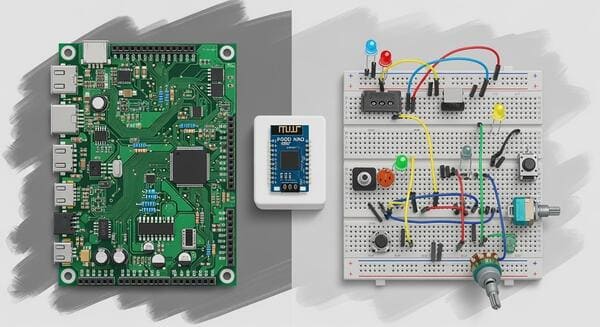
The signal-integrity difference between a breadboard and a PCB is a real electrical effect, not a convenience issue: breadboard spring contacts introduce contact resistance and stray capacitance/inductance in the range of several picofarads and tens of nanohenries per contact point. That's invisible to a slow blinking LED but can distort a fast digital signal, add noise to an analog sensor reading, or destabilize an RF circuit. A good rule of thumb: if your circuit involves a clock or signal above roughly 1MHz, precision analog measurement, or more than an amp or two of current, a breadboard is no longer the right tool, regardless of how it's wired.
Reading a Basic Schematic
A schematic is a circuit's electrical map, not its physical layout, and once you can read one, following build instructions for any project becomes far faster than working from a photo of someone else's breadboard.
Lines represent electrical connections, not physical wire routing or length.
A ground symbol (a downward triangle, or a set of horizontal bars) marks a shared reference point — every ground symbol on the same schematic is the same electrical node.
Component values are usually labeled directly above or beside the symbol (e.g., 330Ω, 100μF, 10kΩ).
Power rails are often shown as horizontal lines running across the top and bottom of the schematic, labeled with their voltage (5V, 3.3V, GND).
A junction dot indicates wires are connected; wires crossing without a dot are not connected.
A Systematic Method for Building Your First Circuit
Building in a fixed sequence — rather than wiring everything at once and hoping — is what separates a project that works on the first try from one that requires hours of guesswork.
1. Define the electrical requirement. Know the supply voltage, the target current for each component, and any timing or signal requirements before you pick up a single part.
2. Select components against that requirement. Use the Ohm's Law and datasheet-rating checks above rather than copying values from an unrelated project.
3. Build the power path first, with nothing else connected. Confirm the correct voltage at every rail with a multimeter before adding a single IC or sensor.
4. Add one subsystem at a time. Wire and test the power supply, then the input stage, then the output stage — verifying each with a multimeter or LED indicator before moving on.
5. Test under realistic conditions. A circuit that works on a bench supply may behave differently on a battery with higher internal resistance, so test with the actual power source you'll use.
6. Document values and pin connections as you go. A simple wiring table or annotated schematic saves significant time if you need to revisit or scale the design.
A Debugging Framework for When Things Don't Work
Every builder hits a circuit that doesn't work on the first try. The difference between a fast fix and an hour of frustration is usually whether you debug systematically or start swapping parts at random.
Systematic Debugging Checklist:
1. Check power first: measure voltage at the supply, then at each downstream rail — a wiring fault often starts here.
2. Verify ground continuity: use the multimeter's continuity mode to confirm every ground point is actually connected to the same reference.
3. Re-check polarity: LEDs, diodes, electrolytic capacitors, and many ICs are polarity-sensitive and will fail silently or visibly if reversed.
4. Isolate by section: disconnect subsystems one at a time until the fault disappears, narrowing the search area instead of testing the whole circuit at once.
5. Inspect solder joints under magnification: a cold joint (dull, grainy surface) or a solder bridge between adjacent pins is one of the most common causes of intermittent faults.
6. Cross-check against the datasheet: confirm the component's actual pinout matches what the schematic assumes — pin numbering errors are easy to make when working from memory.
Safety Practices Worth Building as Habits
Work in a ventilated area when soldering — rosin-core flux fumes are an eye and respiratory irritant with repeated exposure.
Discharge electrolytic capacitors before handling a circuit that's been powered — they can hold a stored charge after power is removed.
Treat any project involving mains (110–240V AC) voltage as a separate skill set requiring dedicated training; low-voltage DC practice does not transfer directly to mains safety.
Use basic ESD precautions (an anti-static wrist strap or at minimum touching a grounded metal surface) before handling MOSFETs, microcontrollers, or other static-sensitive ICs.
Wear eye protection when cutting component leads or stripping wire — clipped lead ends travel further and faster than expected.
A Skill Progression Path
Choosing projects in a deliberate order builds capability faster than jumping straight to an ambitious build. Each tier below assumes you're comfortable with everything in the tier before it.
| Tier | Representative Projects | Core Skills Gained |
|---|---|---|
| Beginner | LED blinker circuit, simple 555-timer oscillator, basic sensor-to-LED indicator | Ohm's Law application, breadboard wiring, multimeter use, reading a simple schematic |
| Intermediate | Microcontroller-based sensor logger, motor control with an H-bridge driver, multi-stage power supply | Component datasheets, perfboard/stripboard soldering, basic firmware, systematic debugging |
| Advanced | Custom PCB layout for a sensor or control board, SMD assembly, multi-board systems with wireless communication | Schematic capture and PCB layout tools, signal integrity considerations, design for manufacturability |
Common Mistakes and the Electrical Reason Behind Each
Skipping the current-limiting resistor calculation: without it, an LED or similar component draws whatever current the supply and its own low internal resistance allow, which usually exceeds its rated maximum almost immediately.
Ignoring absolute maximum ratings on a datasheet: components can survive brief excursions past their rated values but degrade cumulatively, causing failures that appear unrelated and much later.
Treating a breadboard as suitable for any signal speed or current: as covered above, parasitic resistance and capacitance in the contacts becomes significant well before most beginners expect it to.
Under-sizing wire gauge for the expected current: thin wire has higher resistance per foot, which causes voltage drop and heating under sustained load.
Not testing power rails before adding active components: this is the single most effective habit for catching a wiring mistake before it can damage an IC or sensor.
When a Design Outgrows Prototyping and Needs a Custom PCB
Breadboards, perfboard, and stripboard are the right tools for validating a design — but several concrete engineering signals indicate a project is ready to move to a custom PCB rather than staying in prototype form indefinitely:
The circuit needs to be built more than a handful of times identically — hand-wiring introduces variability that a fabricated board eliminates.
Signal frequencies, edge rates, or analog precision requirements are sensitive to the parasitic resistance, capacitance, and inductance inherent in breadboard or point-to-point wiring.
The finished project needs to survive vibration, movement, or field use, where loose spring contacts or hand-soldered joints are a reliability risk.
Component density or a small form-factor requirement makes point-to-point wiring impractical to lay out and debug.
Making that jump means learning schematic capture and PCB layout in dedicated EDA software, understanding trace width for current capacity, and applying basic signal integrity principles like keeping return paths short and separating analog and digital ground where needed. Those are substantial topics in their own right, but recognizing when your project has outgrown a breadboard — rather than continuing to fight it there — is itself a skill worth developing early.
Conclusion
DIY electronics becomes far more predictable once the fundamentals — Ohm's Law, component behavior, platform selection, and systematic debugging — are treated as prerequisites rather than afterthoughts. The specific project you build matters less than the process you build it with: define the electrical requirement, select components against real ratings, build and verify one subsystem at a time, and debug methodically when something doesn't work. That process scales from a first LED circuit all the way to a custom PCB design, and it's the difference between a hobby that stalls at the first stuck project and one that keeps growing in capability.





