日本語
 한국어

FR4 vs Metal Core PCB vs IMS: 2026 Practical Selection Guide
QUICK ANSWER FR4 vs Metal Core PCB comes down to heat density and the thermal path. Choose FR-4 for routing and cost, a metal core PCB for heat spreading, and IMS when a thin dielectric must isolate copper while moving heat into a metal base.
A low-loss laminate such as Panasonic Megtron 6 does not solve every hotspot. Signal integrity and heat removal are separate decisions, so FR4 vs Metal Core PCB selection starts with loss, area, junction limit, and the route to ambient.
FR4 vs Metal Core PCB Basics: What Is FR-4
FR-4 is a flame-retardant glass-reinforced epoxy laminate used for most rigid printed circuit boards.
Routing freedom: Multilayer stackups, plated through-holes, controlled impedance, and dense routing are mature and widely supported.
Moderate heat conduction: Common FR-4 laminates conduct roughly 0.3 to 0.5 W/mK through the dielectric, so copper planes and thermal vias must carry most heat.
Mechanical balance: Glass reinforcement adds stiffness, but thermal cycling can stress vias when Z-axis expansion is poorly controlled.
Cost efficiency: At ordinary power density, FR-4 normally gives the lowest FR4 vs Metal Core PCB material and fabrication cost.
FR4 vs Metal Core PCB Basics: What Is a Metal Core PCB
A metal core PCB uses aluminum, copper, or another metal layer as a structural heat spreader within the board.
Fast lateral spreading: The metal moves heat away from a small source toward a larger mounting area or enclosure.
High stiffness: The base resists bending, which helps LED arrays but limits flex and complicates machining.
Weight: Aluminum is near 2.7 g/cm3 and copper about 8.9 g/cm3, so a copper core adds substantial mass.
Layer options: Single-sided boards are common; multilayer metal core designs are possible but costlier and harder to fabricate.
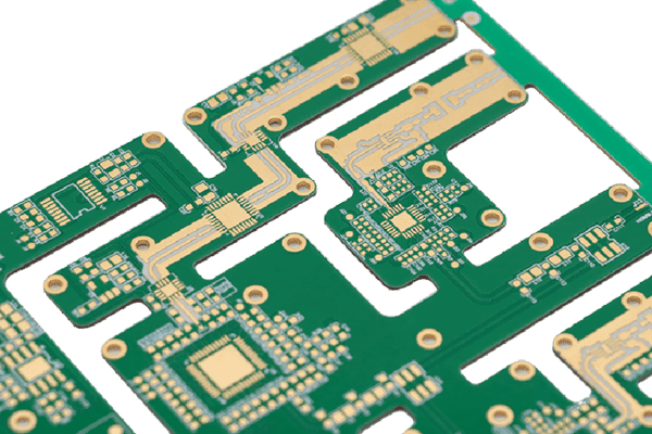
FR4 vs Metal Core PCB Basics: What Is IMS
IMS means insulated metal substrate, usually a copper circuit layer bonded through a thermally conductive electrical insulator to an aluminum or copper base.
Electrical isolation: The dielectric separates live copper from the base and must meet working-voltage and breakdown requirements.
Thermal interface: Conductivity is specified in W/mK, but dielectric thickness and interface quality determine actual thermal impedance.
Compact heat path: A thin dielectric places the heat spreader beneath LEDs, MOSFETs, regulators, or power modules.
Important overlap: IMS is a common type of metal core PCB. In FR4 vs Metal Core PCB vs IMS comparisons, IMS describes the insulated stackup more precisely.
FR4 vs Metal Core PCB vs IMS at a Glance
This FR4 vs Metal Core PCB table keeps the metal core and IMS overlap clear.
| Factor | FR-4 | Metal Core PCB | IMS |
|---|---|---|---|
| Heat path | Copper and vias to a sink | Metal spreads board heat | Thin dielectric into metal base |
| Durability | Good; vias depend on cycling | High stiffness; watch CTE | Strong base; review cycling |
| Size and weight | Light; compact multilayers | Aluminum moderate, copper heavy | Thin; heavier than FR-4 |
| Cost | Usually lowest | Higher material and machining | Driven by dielectric and base |
| Design freedom | Best multilayer routing | Layers and vias constrained | Best for concentrated power |
| Typical uses | Consumer, telecom, controls, medical | LEDs, power, automotive, aerospace | LEDs, converters, motor drives |
Use Cases That Clarify the Difference
FR4 vs Metal Core PCB depends on hotspot location and routing demand. LED lighting and converters benefit from a short path into aluminum. Telecom, controls, and medical devices often favor FR-4 multilayers. Automotive and aerospace power may justify IMS after cycling, vibration, isolation, and mass checks.
FR4 vs Metal Core PCB Thermal Path
FR4 vs Metal Core PCB selection must keep the hottest semiconductor below its junction-temperature limit in the actual enclosure. Map junction, package, solder, copper, dielectric, baseplate, interface, heat sink, and ambient. High W/mK cannot compensate for a thick dielectric, small contact area, poor mounting pressure, or stagnant air.
Screen FR4 vs Metal Core PCB with Rth = t/(kA), then add package and interface resistances. If FR-4 with thermal vias meets margin, IMS may add cost without fixing the limiting interface. If the dielectric dominates, IMS can reduce board resistance.
FR4 vs Metal Core PCB Effects Beyond Heat
The metal base changes mass, stiffness, expansion, machining, grounding, and assembly. Aluminum balances cost and weight. Copper spreads heat better but raises both; steel is stiff but spreads heat poorly.
In an FR4 vs Metal Core PCB review, check creepage near exposed metal, floating versus chassis grounding, and hardware crossing isolation. Ask about dielectric thickness, breakdown rating, copper weight, scoring, burr control, and soldering flatness.
FR4 vs Metal Core PCB Alternative: Ceramic Substrates
Ceramic substrates suit heat flux, isolation, or temperatures beyond polymer dielectrics. Alumina balances insulation and cost; aluminum nitride offers higher conductivity and semiconductor-like expansion.
Ceramics are brittle and expensive. Consider bonded-copper ceramic for power modules, laser diodes, RF power, and high-temperature electronics, but verify metallization, clearance, and mounting stress before replacing IMS.
How to Choose in an FR4 vs Metal Core PCB Design
Choose with a thermal model and assembly constraints, not with a material name alone.
Set the limits. Record ambient, device loss, junction limit, isolation voltage, outline, weight, and cost.
Model the path. Include package, pad, vias or dielectric, interface, heat sink, airflow, and mounting pressure. Use worst-case values.
Start with FR-4. If copper planes, thermal vias, and a heat sink provide margin, FR-4 preserves multilayer routing and lowers cost.
Move to IMS when the board is the bottleneck. Use a thin qualified dielectric, then confirm breakdown voltage and thermal cycling.
Prototype the assembly. Measure the hotspot in the final enclosure. A coupon value is not a finished-product temperature.
For a reliable FR4 vs Metal Core PCB quotation, send PCBgogo the stackup, copper weight, dielectric, base metal and thickness, isolation voltage, finish, and thermal target. Clear inputs support manufacturability review before the prototype locks in the wrong heat path.
The Final FR4 vs Metal Core PCB Decision
FR4 vs Metal Core PCB is a system decision: FR-4 wins on routing and cost, while IMS wins when the board must carry heat into the chassis. Share your thermal target and stackup with PCBgogo to build a manufacturable prototype with fewer late changes.
PCBgogo - Reliable, High-Quality PCB Manufacturing
PCBgogo is a one-stop PCB and PCBA manufacturing factory, helping you save time and costs while ensuring consistent, reliable quality.
Get a Free Quote >
Frequently Asked Questions
Is IMS the same as a metal core PCB?
IMS is usually a metal core PCB with copper, an insulating thermal dielectric, and a metal base. Metal core PCB is broader, so the names overlap but are not always identical.
Can thermal vias change an FR4 vs Metal Core PCB choice?
Thermal vias lower FR-4 resistance when they connect a hot pad to copper planes or a heat sink. They do not remove spreading and interface limits, so validate the path.
Does higher W per mK settle an FR4 vs Metal Core PCB choice?
No. Thickness, area, copper spreading, interface resistance, and heat-sink conditions can outweigh conductivity. Compare thermal impedance for the intended construction.
When should ceramic replace IMS?
Use ceramic when a polymer dielectric cannot meet heat-flux, isolation, temperature, or expansion requirements. The gain must justify cost, brittleness, and tighter mechanical rules.