




 日本語
日本語
 한국어
한국어

FPC TWS Guide for Reliable Earbud Design and Production
QUICK ANSWER An FPC TWS design succeeds when the flexible circuit is chosen around the earbud shape, bend duty, signal return path, and assembly load. The right solution is not simply the thinnest flex. It is the layout and manufacturing plan that still works after charging cycles, enclosure compression, and production variation.
Introduction: Why TWS Interconnect Problems Often Appear Late
A true wireless earbud is a very small mechanical system with very little free volume. The battery, rigid board, antenna, microphones, touch zone, speaker, and charging contacts all compete for space, and their tolerance stack can push load into a flex bend or pad root.
A prototype that powers on is not automatically a production-ready product. This FPC TWS guide explains the architecture choices, validation steps, and manufacturing controls that turn a fit check into a reliable release decision.
What Is an FPC TWS Assembly
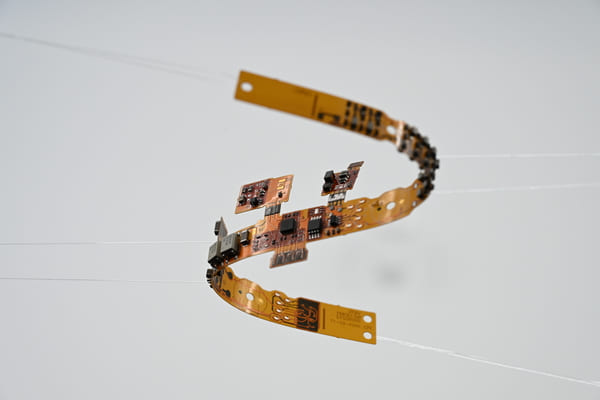
An FPC TWS assembly is a flexible printed circuit used inside true wireless earbuds or their charging cases to connect the battery, contacts, sensors, speaker, microphones, and small rigid boards. Its common building blocks are polyimide film, copper foil, coverlay, and local stiffeners, each selected to manage electrical routing and mechanical load.
A static flex can follow the inner enclosure wall, while a dynamic flex must be designed around repeated movement. For repeated bending, a practical starting point is a bend radius of about ten times the finished flex thickness, with pads, vias, coverlay openings, and stiffener edges kept out of the active bend zone. This is a starting rule, not a replacement for product-level testing.
How Three TWS Earbud Types Change FPC Cost and Layout
Earbud form factor changes the acoustic seal, microphone placement, routing length, and mechanical loading. The table compares common consumer positioning; the price bands are retail reference points only, not BOM costs or factory quotations.
| Earbud type | User advantage | FPC design priority | Typical retail positioning |
|---|---|---|---|
| Semi in ear | Light feel and open fit. | Mostly static links. Protect the battery and touch area from compression. | US$20 to US$80 |
| In ear | Strong passive seal and a good base for ANC. | Dense microphone and contact areas need bend, stiffener, and adhesive clearance. | US$40 to US$150 |
| Open ear or ear hook | Natural awareness and stable sport fit. | Longer routing requires bend life validation near the hook or loaded area. | US$70 to US$200 plus |
Once the form factor is fixed, the team can decide whether the circuit experiences dynamic bending rather than discovering that constraint after the enclosure is frozen.
Why FPC Is Becoming More Important in TWS Products
FPC matters in TWS products because it gives the designer controlled routing through a three-dimensional enclosure without relying on hand-wired connections. It can separate microphone, touch, charging, and battery locations from the main board shape, which is particularly useful when the acoustic layout and antenna position need room to move.
Space efficiency: A flex can follow a curved shell and reduce the need for bulky board area or additional connectors.
Placement freedom: The flex makes it easier to place microphones around an acoustic path while keeping the main board in a protected location.
Assembly discipline: A defined flex profile provides more repeatable routing than loose wires, provided the fold order and adhesive locations are documented.
Reliability tradeoff: The same flexibility that saves space can create fatigue risk when the bend area, stiffener boundary, or coverlay opening is poorly placed.
Those benefits make FPC a structural and electrical component, not just a cable. That is why the architecture decision must happen before tooling and final enclosure clearances are released.
How to Choose the Right FPC TWS Architecture
The right FPC TWS architecture is determined by movement, signal behavior, assembly force, and cost drivers together. Use the following decision sequence before finalizing the stackup or requesting a production quote.
1. Define the bend duty: Mark every static and dynamic zone, then state the expected bend angle and cycle condition. A dynamic zone should favor continuous traces and should not carry pads, vias, or a stiffener edge.
2. Map the signal paths: RF, digital, power, and sensitive microphone paths should not be treated as identical routes. Preserve a continuous return reference where required and avoid forcing critical paths through a narrow bend region.
3. Design for actual assembly load: Add PI or FR4 stiffening below connectors, contacts, or buttons when the enclosure and fixture load require it. Include enclosure clearance, adhesive thickness, and contact force in the drawing rather than assuming the flex will absorb every tolerance.
4. Compare total cost drivers: Layer count, copper weight, flex area, stiffeners, finish, testing, and processing complexity all influence cost. A small flex is not automatically a low-cost flex when its duty cycle or assembly risk is high.
This sequence naturally leads into the validation plan. When these inputs are stated early, DFM discussion can focus on a stable product rather than a nominally manufacturable drawing.
A Practical FPC TWS Solution from Gerber to Production
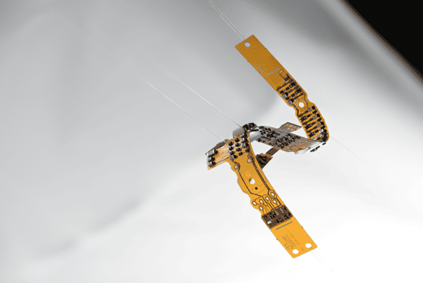
A practical FPC TWS solution connects design files, first article checks, and production inspection in one loop. Sending Gerber alone leaves the manufacturer without the information needed to judge bend reliability or assembly risk.
1. Prepare the input pack: Include the outline, bend lines, stackup, stiffener locations, assembly direction, key dimensions, and validation requirements with the Gerber data.
2. Run a focused DFM review: Check line width and spacing, coverlay opening, exposed pads, the distance from vias to fold lines, and profile tolerance. Correct the load path first instead of making the entire flex thicker as a quick fix.
3. Validate in the real product: Test the first article in the actual enclosure, adhesive process, and fixture. Verify continuity, finished stack height, contact pressure, charging cycles, bending, and the finished product function.
4. Lock the production feedback loop: Tie revision number, inspection points, failure photos, and failure location together. This turns an intermittent symptom into a traceable issue at a specific pad, fold, or assembly operation.
When this pack is complete, a team can use PCBgogo conversations to confirm manufacturability boundaries, first article comparison points, and revision control expectations. The value lies in comparing a complete manufacturing condition rather than comparing a bare unit price.
Which Quality Standards Help Evaluate an FPC TWS Design
FPC TWS quality is evaluated through a stack of design, performance, and visual acceptance requirements rather than through a single certificate. The following standards give engineering and inspection teams a common language.
IPC-2223: Provides sectional design guidance for flexible printed boards, including conductors, holes, spacing, and flexible areas.
IPC-6013: Defines performance and specification requirements for flexible and rigid flex printed boards, useful when setting manufacturing performance boundaries.
IPC-A-600: Supports printed board acceptability decisions and helps inspection teams identify visual and process-related conditions.
Standards do not replace product-level validation. A TWS project still needs the actual enclosure and use motion to test contact compression and dynamic bending together.
Customer Feedback: How an Intermittent Charging Fault Was Solved
An earbud that charges only when pressed into the case often has an intermittent flex failure near the contact area, not a random battery fault. In one common pattern, the unit worked after manual pressure but failed again after repeated take out and return cycles.
The failure mechanism was mechanical. The gold finger region carried both contact pressure and enclosure compression, while the stiffener did not cover the loaded area and the coverlay opening ended too close to the pad root. Small repeated deflection initiated copper fatigue, and pressure temporarily restored the electrical contact.
The corrective action was not to thicken the complete flex. The contact load zone was moved onto the stiffened region, the coverlay opening was pulled back from the pad root, the fold was moved away from the pad, and an assembled charging cycle plus bend test was added. That sequence removes the cause chain from concentrated load to copper fatigue to intermittent open circuit.
Why PCBgogo Fits an FPC TWS Manufacturing Workflow
PCBgogo is most useful in an FPC TWS project when the supplier discussion is tied to concrete design and production decisions. The objective is not a generic supplier comparison. It is a clear handoff from the drawing to the first article and then to a controlled production revision.
Confirm the manufacturing condition: Align material, layer count, copper thickness, coverlay, stiffening, profile tolerance, and electrical test boundary before comparing quotations.
Use a first article checklist: Review bend lines, assembly direction, stiffener placement, and key dimensions so a sample is assessed for fit and function, not continuity alone.
Maintain change traceability: Connect revision control and issue feedback to the inspection plan, making repeated production problems easier to isolate and correct.
This approach treats the FPC as a shared design and manufacturing component. It reduces the chance that the enclosure, fixture, and circuit need to be changed together after the product is already close to release.
PCBgogo - Reliable, High-Quality PCB Manufacturing
Save time and money with an all-in-one solution for PCB fabrication, assembly, and parts. Reduce vendor coordination, avoid split shipments, and get consistent, reliable quality.
Get Free Quote >
FPC TWS Frequently Asked Questions
The questions below address the design choices that most often affect bend life, stackup selection, stiffening, and first article validation.
Can a dynamic FPC bend area contain vias?
It is better to avoid vias in a dynamic bend area. A via and its surrounding geometry create local stiffness and stress concentration, so the bend zone should remain as uniform and continuous as possible.
Should a TWS earbud use a single-layer or double-layer FPC?
Simple fixed interconnects can use a single-layer or double-layer static FPC. When several signals must cross a complex space, a double-layer design often makes return path control and routing separation easier.
Does a thicker stiffener always improve reliability?
No. A stiffener should support the connector, contact, or other loaded area without creating an unnecessary hard transition or stack height problem. The enclosure and the flex should be designed as one tolerance system.
What should an FPC TWS first article test include?
At minimum, test continuity, assembled stack height, contact pressure, charging cycles, and bending. ANC or wireless products should also be checked in their finished acoustic and RF condition.
Conclusion
The best FPC TWS choice starts with the earbud form factor and ends with a validated production loop. Define movement, return paths, load zones, stiffening, and test conditions early, then use PCBgogo manufacturing conversations to keep those requirements traceable through first article and production release.





