
 日本語
日本語
 한국어
한국어

Electro-Optic Modulators: How They Work and Why the Driver PCB Matters as Much as the Crystal
An electro-optic modulator (EOM) is one of the fastest and most precise ways to control light with an electrical signal, used in everything from fiber-optic transceivers to laser Q-switches and frequency-stabilized reference cavities. Most technical references cover the crystal physics behind these devices in depth: the Pockels effect, birefringence, and half-wave voltage. Far fewer address the printed circuit board that actually carries the modulating signal to the device. In practice, an EOM is only as fast, stable, or clean as the driver circuit feeding it. This guide covers both sides: how electro-optic modulation works, and the PCB design choices that determine whether a driver circuit delivers on that potential.
What Is an Electro-Optic Modulator?
An electro-optic modulator controls the intensity, phase, or polarization of a laser beam using an applied electric field rather than any moving part. Most EOMs rely on the linear electro-optic effect, commonly called the Pockels effect: an electric field applied across a nonlinear crystal changes the crystal's refractive index in direct proportion to the field strength. Because the effect is linear and essentially instantaneous, EOMs can modulate light far faster than mechanical or thermal alternatives, reaching into the gigahertz range for integrated devices.
A related but distinct category is the electro-absorption modulator, which changes a semiconductor's optical absorption under an applied field (the Franz–Keldysh effect) rather than its refractive index. Electro-absorption modulators are common in compact transceivers, but the term "EOM" generally refers to Pockels-effect devices, which is the focus of this article.
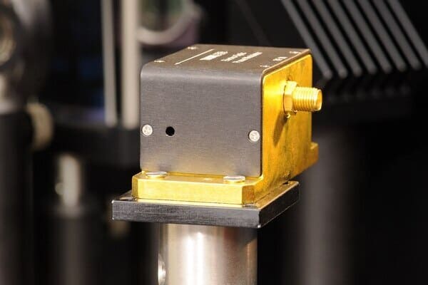
The Crystal and the Half-Wave Voltage
The key figure of merit for any Pockels cell is the half-wave voltage, Vπ, the voltage needed to shift the phase of light passing through the crystal by exactly π radians. For bulk crystal cells, Vπ is often several hundred to several thousand volts, which is why bulk EOMs require a dedicated high-voltage driver rather than a standard signal generator. Integrated waveguide modulators, by contrast, confine light to a narrow channel between closely spaced electrodes. The shorter electrode gap dramatically lowers Vπ, sometimes to just a few volts, which is one reason integrated lithium niobate and thin-film lithium niobate (TFLN) modulators dominate high-speed optical communications.
| Material | Notable Property | Typical Use |
|---|---|---|
| KD*P (DKDP) | High laser damage threshold | Q-switching, pulse picking |
| KTP | Good thermal stability | Laser Q-switches |
| BBO | Handles high average power and switching frequency | High-repetition-rate systems |
| LiNbO3 | Strong electro-optic coefficient, waveguide-compatible | Telecom modulators, integrated optics |
| LiTaO3 | Similar to LiNbO3, lower birefringence | Specialty modulators |
| ADP | Low material cost | Legacy Q-switch designs |
Three Ways to Modulate Light
Phase Modulation
The simplest EOM configuration is a bare Pockels cell aligned so the input polarization matches one of the crystal's optic axes. The applied voltage delays the optical phase without altering polarization or amplitude. Phase modulators are widely used for frequency-stabilization techniques such as the Pound–Drever–Hall method, where a small sideband is imposed on a laser to lock it to a reference cavity.
Polarization Modulation
When the crystal is oriented so the induced phase shift depends on polarization direction, the Pockels cell behaves as a voltage-controlled waveplate. A linearly polarized input becomes elliptically polarized, and with the right drive voltage a full 90° polarization rotation is possible. This configuration underlies polarization scramblers and switches.
Amplitude and Intensity Modulation
Pairing a polarization-modulating Pockels cell with a polarizer converts polarization changes into a transmitted power change, the standard architecture for an intensity modulator. In integrated photonics, the same result is often achieved by placing a phase modulator in one arm of a Mach–Zehnder interferometer, converting phase modulation into amplitude modulation through interference. Mach–Zehnder modulators dominate high-speed fiber-optic transmitters because they hold phase stability better than free-space designs.
| Type | Core Mechanism | Typical Application |
|---|---|---|
| Phase | Direct phase delay | Laser locking, frequency combs |
| Polarization | Voltage-controlled waveplate | Polarization scrambling and switching |
| Amplitude / Intensity | Pockels cell + polarizer, or Mach–Zehnder interferometer | Data transmission, Q-switching, pulse picking |
Bulk vs. Integrated Waveguide Modulators
EOMs split broadly into two mechanical architectures. Bulk modulators pass a free-space or fiber-coupled beam through a crystal with plate electrodes, and are common in laser labs for Q-switching, cavity dumping, and pulse picking. Integrated waveguide modulators etch or diffuse an optical channel into an electro-optic material such as lithium niobate, placing electrodes close enough to the waveguide to modulate with much lower voltage and much higher bandwidth.
For the highest bandwidths, tens of gigahertz, waveguide modulators use traveling-wave electrodes, where the RF drive signal propagates alongside the optical signal rather than being applied as a static field. Matching the phase velocity of the microwave and optical waves along the electrode length is what allows these devices to maintain efficient modulation even when the electrode is many RF wavelengths long.
| Attribute | Bulk (Free-Space) | Integrated Waveguide |
|---|---|---|
| Typical Vπ | Hundreds to thousands of volts | Single-digit to tens of volts |
| Bandwidth | kHz–MHz (lower for resonant types) | GHz range, up to tens of GHz |
| Common use | Q-switching, cavity dumping | Telecom, high-speed data transmission |
| Driver type | High-voltage pulse or resonant driver | RF traveling-wave driver |
Why the Driver Circuit Decides Real-World Performance
An EOM crystal only performs as well as the electrical signal reaching it. Because a Pockels cell is electrically a capacitor, its capacitance, combined with the driver's output impedance, sets an RC time constant that limits how fast the device can switch, independent of the crystal's intrinsic response time. Reducing that capacitance is a core design goal for fast-switching applications, but it has to be balanced against the driver's ability to supply the current a low-capacitance, high-voltage load demands.
Applications that need a fixed-frequency sinusoidal modulation often use a resonant driver built around an LC circuit, which can generate a much larger voltage across the crystal than the driver's own input voltage, at the cost of losing tunability, since changing the modulation frequency means swapping a component. Broadband drivers trade that voltage gain for flat response across a wide frequency range, typically starting near DC. Many modulators also need automatic bias control circuitry to correct for thermally induced drift in the operating point, adding another layer of electronics between signal source and crystal.
PCB Design Considerations for EOM Driver Circuits
Because EOM drivers combine high voltage, high frequency, and precision bias control on one board, the printed circuit board itself becomes a limiting factor in system performance. A few considerations recur across driver designs.
Controlled Impedance for RF and Traveling-Wave Signals
Broadband and traveling-wave drivers typically target a 50-ohm characteristic impedance to match the modulator's RF electrodes. Any mismatch along the signal path, from connector to trace to bond wire, reflects part of the drive signal back toward the source, degrading rise time and introducing ripple in the transfer function. This makes stripline or microstrip geometry, trace width, and dielectric selection a first-order design decision rather than an afterthought.
High-Voltage Clearance and Creepage
Bulk-crystal drivers routinely switch hundreds to thousands of volts across the Pockels cell. Trace spacing, creepage distances along the board surface, and clearance around high-voltage components all need margin well beyond what a typical low-voltage digital board would use, and conformal coating is common on exposed high-voltage traces to prevent arcing in humid environments.
Managing Parasitic Capacitance
Every extra millimeter of trace, every via, and every connector pad on the driver board adds parasitic capacitance in parallel with the modulator's own capacitance. For fast-switching applications, this stray capacitance can dominate the RC time constant as much as the crystal itself, so driver layouts for fast EOMs favor short, direct signal paths and minimal via count between the output stage and the modulator connector.
Thermal Stability for Bias Circuits
Automatic bias control depends on a stable reference, and temperature gradients across the board can shift that reference just as much as temperature drift in the crystal itself. Adequate copper pour, thermal relief under power components, and physical separation between the high-power output stage and sensitive bias-sensing circuitry all help keep the control loop accurate over time.
Fabrication Notes: Driver boards of this kind, mixing high-voltage sections with tightly toleranced RF traces, are a good fit for fabrication processes built around verified impedance control. PCBgogo, for example, offers HDI fabrication and a free DFM check that flags clearance or impedance issues before a board goes to production, alongside standard AOI and AXI inspection and a pre-shipment E-test to confirm continuity on completed boards.
Common Applications of Electro-Optic Modulators
EOMs show up anywhere light needs to be controlled at electronic speeds:
High-speed optical communications, where intensity or phase modulators encode data onto a laser carrier
Laser Q-switching, where an EOM blocks the resonator until a pulse is ready to be released
Cavity dumping and pulse picking, selecting individual pulses from a train of ultrashort pulses
Laser frequency stabilization, such as the Pound–Drever–Hall locking technique
Active mode locking, where the modulator drives resonator losses or phase at the cavity round-trip frequency
| Application | Modulation Type Used | Key Requirement |
|---|---|---|
| Optical data transmission | Amplitude (Mach–Zehnder) | High bandwidth, low Vπ |
| Q-switching | Amplitude (switch) | High extinction ratio |
| Pulse picking | Amplitude (switch) | Nanosecond-scale rise time |
| Frequency stabilization | Phase | Small, precise phase modulation |
| Mode locking | Phase or amplitude | Sync to cavity round-trip frequency |
Frequently Asked Questions
What is the difference between an electro-optic modulator and an acousto-optic modulator?
An EOM uses an electric field to change a crystal's refractive index directly through the Pockels effect and can switch in nanoseconds or less. An acousto-optic modulator uses a sound wave in a crystal to diffract light, an approach that is generally slower but simpler to drive from a fixed RF frequency.
What is half-wave voltage (Vπ)?
Vπ is the voltage required to shift the optical phase through a Pockels cell by π radians, or 180°. A lower Vπ means less driver voltage is needed for full modulation depth, which is why integrated waveguide modulators, with their narrow electrode gaps, are prized for low-voltage, high-speed operation.
Can an electro-optic modulator change the frequency of light?
Only briefly. Phase modulation shifts frequency only while the phase is actively changing, so an EOM cannot produce a sustained frequency shift, which would require an unbounded, ever-increasing phase delay. Continuous frequency shifting is typically handled by acousto-optic modulators instead.
Why does the PCB matter as much as the crystal in an EOM system?
The crystal sets the theoretical modulation bandwidth and voltage requirement, but the driver board's impedance control, parasitic capacitance, and thermal stability determine how much of that theoretical performance actually reaches the modulator.





