
Copper Clad Laminate (CCL): The Complete Guide to PCB's Foundation Material
Every printed circuit board starts life as a flat, unassuming sheet: copper foil bonded to an insulating substrate. That sheet is called copper clad laminate (CCL), and it is arguably the single most important material decision in any PCB project. Get it right, and your board runs cool, signals stay clean, and yields stay high. Get it wrong, and you can end up with delamination, signal loss, or boards that fail thermal cycling in the field.
This guide breaks down exactly what copper clad laminate is, how it's built and manufactured, the major classifications you'll run into when selecting material, and the properties that separate a reliable CCL from a mediocre one. Whether you're a design engineer specifying a stackup or a procurement manager sourcing your next PCB build, you'll walk away knowing how to talk to your fabricator about CCL — and how PCBgogo helps you get it right the first time.
What Is Copper Clad Laminate?
Copper clad laminate is a composite panel made by bonding a thin layer of copper foil onto one or both sides of a dielectric (non-conductive) substrate under heat and pressure. The substrate is typically a reinforcing material — most commonly woven fiberglass cloth — impregnated with resin, such as epoxy, polyimide, or PTFE.
In short, CCL is the raw "blank canvas" PCB manufacturers start with. During fabrication, unwanted copper is etched away through a photolithography and etching process, leaving behind the traces, pads, and planes that form your circuit. Everything about how a board performs electrically, mechanically, and thermally traces back to the quality and specification of the CCL it was built on.
The Structure of Copper Clad Laminate
A standard CCL is built from three functional layers:
Copper foil – the conductive layer that will become circuit traces, typically 0.5 oz to 3 oz per square foot (roughly 17–105 μm) for standard boards, thicker for power applications.
Dielectric substrate (core) – provides electrical insulation and mechanical rigidity. This is the reinforcing material (glass fiber cloth or paper) fully impregnated and cured with resin.
Adhesive layer – bonds copper to the substrate in many constructions. High-frequency and flexible CCLs often skip this layer entirely ("adhesiveless" CCL) to reduce signal loss and improve reliability.
A closely related material worth understanding is prepreg ("pre-impregnated" fiberglass cloth soaked in B-staged resin). Prepreg isn't the finished CCL itself — it's the semi-cured bonding sheet used both inside CCL production and later to glue multiple layers together when building multilayer PCBs.
How Copper Clad Laminate Is Manufactured
CCL production is a precise, multi-stage process, and even small deviations affect the final board's reliability:
1. Resin preparation – Epoxy, polyimide, or PTFE resin is formulated and mixed to the required chemistry and viscosity.
2. Substrate impregnation – Woven fiberglass cloth (or alternative reinforcement) is impregnated with the resin solution, then excess resin is removed for a uniform coating.
3. B-staging (drying/partial curing) – The impregnated sheet is heated just enough to partially cure, producing prepreg that is rigid but still able to flow and bond under heat and pressure.
4. Lamination – Copper foil is placed on one or both sides of the prepreg stack, then pressed under high temperature and pressure. This fully cures the resin and permanently bonds the copper to the substrate.
5. Cooling and trimming – The laminated panel is cooled gradually to relieve internal stress, then trimmed to standard panel dimensions.
6. Inspection and surface treatment – Panels are checked for thickness, flatness, and surface defects, then treated (such as anti-oxidation coating) to protect the copper before it reaches the fabricator.
Any inconsistency in resin content, gel time, or pressing conditions during this process can translate directly into warped boards, poor copper adhesion, or electrical failures downstream — which is exactly why PCBgogo sources CCL exclusively from qualified, IPC-4101 certified suppliers and verifies incoming material before it enters production.
How Copper Clad Laminate Is Classified
CCL comes in dozens of variants. Here's how the industry typically categorizes them:
By Mechanical Rigidity
Rigid CCL (e.g., FR-4, CEM-1, CEM-3) — used for standard rigid PCBs.
Flexible CCL (e.g., polyimide-based) — used for flex circuits.
Rigid-flex CCL — combines both, used in flex-rigid PCB stackups.
By Reinforcing Material
Glass fiber cloth-based (FR-4, FR-5) — the most common, offering strong mechanical and dielectric performance.
Paper-based (XPC, FR-1) — lower cost, used in simple consumer electronics.
Composite (CEM-1, CEM-3) — a blend of glass and paper for a balance of cost and performance.
By Resin System
Epoxy resin CCL (FR-4, CEM-3) — the industry workhorse for general-purpose PCBs.
Phenolic resin CCL (FR-1, XPC) — economical, but limited thermal performance.
Polyimide CCL — high heat resistance, common in flex and aerospace applications.
PTFE (Teflon) CCL — extremely low dielectric loss, used for RF and microwave boards.
BT (Bismaleimide Triazine) resin — high-Tg option for advanced IC substrates.
By Base Material
Organic resin CCL — standard FR-4 family.
Metal-base CCL — aluminum or copper core for superior heat dissipation in LED and power electronics.
Ceramic-base CCL — used for extreme thermal and high-frequency demands.
By Special Function
Halogen-free CCL – chlorine and bromine content controlled below regulatory thresholds, offering better heat resistance and dimensional stability, at a slight tradeoff in peel strength.
Lead-free / RoHS-compliant CCL – formulated for lead-free soldering profiles, using PN curing systems for improved thermal decomposition resistance versus traditional DICY-cured laminates.
High-Tg CCL – glass transition temperature above 170°C, critical for multilayer boards, automotive, and any application exposed to repeated thermal cycling.
High-frequency / low-loss CCL – low Dk (dielectric constant) and Df (dissipation factor) materials, essential for RF, 5G, and high-speed digital designs.
What Makes a High-Quality Copper Clad Laminate?
Not all CCL performs the same, even within the same material family. A quality laminate needs to satisfy five categories of requirements:
Appearance – Flat, smooth copper foil free of dents, pinholes, wrinkles, or resin spots. Surface defects propagate directly into etching and plating defects.
Dimensional accuracy – Consistent length, width, thickness, and minimal warpage/twist, since even small deviations compound across a multilayer stackup.
Electrical performance – Stable dielectric constant (Dk), low dissipation factor (Df), high insulation and surface resistance, and adequate dielectric breakdown voltage — all crucial for signal integrity, especially at high frequency.
Physical/mechanical performance – Strong peel strength (copper-to-substrate bond), good bending strength, and reliable heat resistance (Td, T260, T288) so the board survives soldering and rework without delaminating.
Chemical & environmental performance – Proper Tg, low Z-axis CTE (thermal expansion), flame retardance (UL 94 V-0), chemical resistance, and low moisture absorption.
Reputable fabricators test incoming CCL against IPC-4101 (base material specification) using IPC-TM-650 test methods, and check flex-specific material against IPC-4204. At PCBgogo, every laminate batch is verified against these standards before it's released to production — so the material properties you specify on paper are the properties you actually get on your finished board.
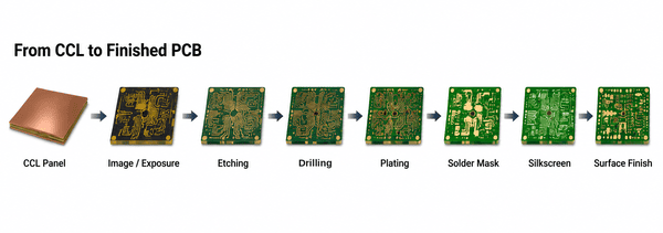
CCL vs. PCB: What's the Difference?
It's a common point of confusion: copper clad laminate is the starting material; a printed circuit board is the finished product. CCL becomes a PCB only after a series of subtractive and additive processes — imaging, etching, drilling, plating, solder mask application, silkscreen printing, and surface finishing. Choosing the right CCL is the foundation of that process, but it's only step one of a much longer manufacturing journey.
How to Choose the Right CCL for Your Project
When specifying CCL — or trusting your fabricator to spec it for you — weigh these factors:
Operating frequency: Standard FR-4 is fine below a few GHz. High-speed digital and RF/microwave designs need low-Dk, low-Df materials to control impedance and minimize insertion loss.
Thermal environment: Power electronics, LED boards, and automotive applications benefit from metal-core CCL or high-Tg FR-4 to manage heat and resist thermal cycling stress.
Mechanical requirements: Wearables and dynamic-flex applications require flexible or rigid-flex CCL rather than standard rigid laminate.
Layer count: Multilayer boards place higher demands on dimensional stability and Z-axis CTE, since misregistration compounds with every additional layer.
Regulatory requirements: RoHS, REACH, UL 94, and halogen-free requirements may be mandated by your target market or industry (automotive, medical, aerospace).
Cost vs. performance: Not every board needs exotic material. Overspecifying CCL adds cost without adding value; underspecifying risks reliability. This is exactly where an experienced fabrication partner adds value in the DFM review.
Why CCL Selection Matters More Than Most Designers Realize
It's easy to treat material selection as an afterthought once the schematic and layout are done. In practice, CCL choice affects:
Signal integrity — Dk/Df instability causes impedance mismatches and signal loss, especially above a few hundred MHz.
Manufacturing yield — Poor dimensional stability leads to registration errors across layers, directly impacting yield on multilayer builds.
Field reliability — Inadequate Tg or peel strength shows up months later as delamination, cracked vias, or intermittent opens under thermal stress — failures that are expensive to trace back to a material decision made early in the project.
This is why sourcing CCL from a fabricator with tight incoming-material quality control isn't a "nice to have" — it's a direct driver of board reliability.
Get Reliable Copper Clad Laminate PCBs with PCBgogo
Choosing the right copper clad laminate is critical, but it only pays off if your fabricator handles it correctly from there. At PCBgogo, we work exclusively with qualified, IPC-4101-certified CCL suppliers and verify every incoming batch against dielectric, thermal, and mechanical specifications before it enters production. Whether your project calls for standard FR-4, high-Tg material, halogen-free laminate, or metal-core substrates for thermal management, our engineering team helps you select the right CCL for your application — then fabricates it with tight process control from prototype through volume production.
With fast turnaround, transparent instant online quoting, and a track record across consumer electronics, automotive, industrial, and RF applications, PCBgogo makes it simple to turn the right material choice into a reliable finished board.
Get an Instant PCB Quote and reach out to our engineering team to discuss the best copper clad laminate for your next design.
Frequently Asked Questions
What is the difference between CCL and prepreg?
CCL is the finished copper-foil-clad panel used to start PCB fabrication. Prepreg is the semi-cured, resin-impregnated fiberglass sheet used both to manufacture CCL and to bond multiple layers together in multilayer PCB stackups. Prepreg has no copper foil of its own.
Is FR-4 the same as copper clad laminate?
FR-4 is one specific type of copper clad laminate — a glass-fiber-reinforced epoxy laminate — and by far the most widely used one. CCL is the broader category that also includes CEM, polyimide, PTFE, metal-core, and ceramic-base materials.
How thick is copper clad laminate?
Core thickness commonly ranges from around 0.1mm to over 3mm for rigid boards, while copper foil weight is typically specified separately, from 0.5 oz (about 17μm) up to several ounces for high-current designs.
Does CCL choice affect PCB cost?
Yes. Standard FR-4 is the most economical option; high-Tg, halogen-free, metal-core, and low-loss RF laminates all carry a cost premium proportional to their added performance. A good fabricator will help you avoid overspecifying material your application doesn't actually need.


