日本語
 한국어

Beveled Edge Guide for Better CNC Machined Parts
KEY DEFINITION A beveled edge is a sloped surface that replaces a square edge on a part. It can guide assembly, remove an exposed sharp corner, or prepare a joint for welding. For CNC manufacturing, specify the angle, size, location, and tolerance so the finished edge performs its intended function.
A shaft that catches during insertion or a housing that feels sharp may need a better edge detail. This guide explains how to choose an edge profile, communicate its geometry, and avoid machining costs that add little value.
Bevel, Chamfer, and Fillet: Which Profile Fits?
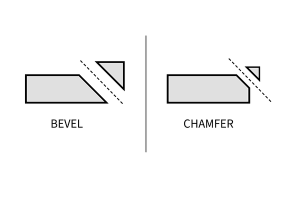
A bevel and a chamfer both create an angled face; a fillet creates a curved transition. In shop usage, "chamfer" often describes a small corner cut, while "bevel" may describe a broader slope. These terms overlap, so dimensions matter more than the label.
A chamfer is not restricted to 45°. The comparison below gives practical starting points.
| Edge profile | Geometry | Typical design purpose |
|---|---|---|
| Bevel | Sloped face, sized to suit the part | Weld preparation or an angled interface |
| Chamfer | Flat corner cut, commonly 45° | Insertion guidance or a small edge break |
| Fillet | Curved transition with a radius | Smooth contact or stress management |
Choose the profile around the contact conditions and remaining material, rather than appearance alone.
Where Does a Beveled Edge Add Value?
A beveled edge is useful when its slope solves a specific assembly, handling, joining, or appearance problem.
Shaft and bushing entry: A lead-in helps a shaft enter a mating bore. Preserve the cylindrical engagement length needed for the fit.
Removable enclosure lids: A controlled edge break reduces exposed sharpness during servicing. Check the new boundaries for burrs after machining.
Welded plate joints: Beveling improves access to the joint root. Choose the bevel angle and root gap to suit the welding process and plate thickness.
Visible control panels: A consistent sloped border creates a deliberate highlight. Specify its width and finish when adjoining panels must look uniform.
These applications need different geometries. A decorative border should not determine the dimensions of a weld preparation or precision lead-in.
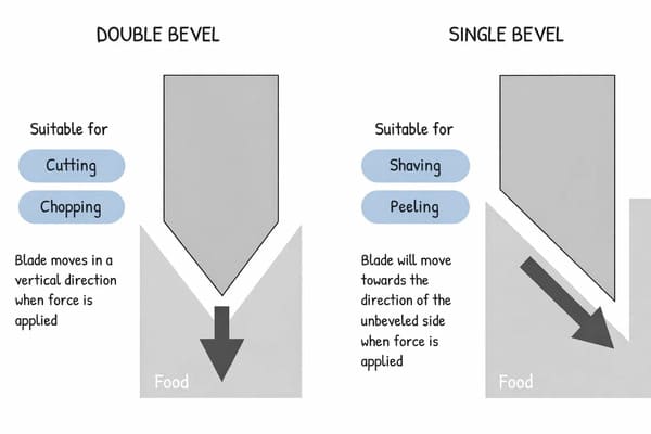
A single bevel removes material from one side; a double bevel treats both sides. On thin sections, preserve an intentional flat land instead of allowing opposing cuts to create a fragile knife edge. Choose symmetry when the assembly or joint design needs it.
How CNC Machines Cut an Angled Edge
CNC milling produces a beveled edge by moving a suitable cutter along the selected contour; turning produces comparable features on rotational parts such as shafts. Accessible edges often suit 3-axis milling, while complex orientations may benefit from additional axes or another setup.
Pay attention to the difference between included and per-side cutter angles. A symmetrical cutter with a 90° included angle has a 45° angle on each side of its axis. When selecting a tool, also check clearance to avoid interference with nearby walls or fixtures.
Material affects the cutting strategy. Chip evacuation, sharp tooling, and appropriate engagement matter for both metals and plastics; simply reducing feed is not a universal solution to poor edge quality. A stable setup and suitable toolpath help control width and surface consistency.
With the machining approach understood, the drawing needs to define what the shop should produce.
How to Specify a Beveled Edge Without Guesswork
A usable bevel specification defines measurable geometry and acceptance requirements. Before requesting a quote, check four details:
Dimension meaning: Identify the angle reference and whether the linear dimension is a setback, depth, or sloped face width. As an illustrative right-angle example, a 0.5 mm × 45° chamfer has 0.5 mm setbacks on both adjacent faces; its sloped face measures approximately 0.707 mm across the section. Those dimensions are not interchangeable.
Functional limits: Model fit-critical features and state applicable size and angle tolerances. Preserve sealing lands, thread engagement, and minimum wall thickness. Avoid demanding the tightest tolerance on every cosmetic edge, because additional process control and inspection can increase cost.
Tool access: Identify underside edges, interrupted contours, and bevels beside tall walls. Clearance must accommodate the cutter and holder throughout the path. Standardize sizes and angles where function allows to reduce tool changes and setup complexity.
Final condition: State burr limits, finish requirements, and whether dimensions apply after coating. A general deburring note does not define a functional bevel, and a low surface roughness value alone does not establish that an edge is burr-free.
For a critical feature, agree on how the angle and size will be checked. An optical profile measurement may suit a small chamfer; larger accessible faces may support other dimensional inspection methods. The acceptance method should match the drawing and required accuracy.
How PCBgogo Supports Your Edge Specifications
PCBgogo combines CNC machining, manufacturability review, and finishing services to help turn defined edge requirements into custom parts. Its published capabilities support several practical priorities:
Process flexibility: 3-axis, 4-axis, and 5-axis CNC milling, alongside CNC turning, provide options for housings, panels, shafts, and more complex components.
Review and inspection: DFM evaluation and dimensional inspection help address thin walls and difficult access before cutting, then check parts against the drawing. First article inspection reports are available on request.
Material and finish choices: Metals and engineering plastics can be paired with compatible finishes, including anodizing, bead blasting, polishing, and passivation. This helps coordinate edge geometry with appearance and service conditions.
Prototype support: PCBgogo states that simple parts can ship in as little as 48 hours. Material, quantity, geometry, and finishing requirements determine the actual schedule.
A successful beveled edge starts with a clear purpose and an unambiguous drawing. Request a CNC machining quote with your CAD model, drawing, material, quantity, and finish requirements so the team can review the route from prototype to production.
Common Questions About Beveled Edges
The right edge detail depends on geometry and function. These answers address common design decisions.
Is a beveled edge always safer to touch?
No. Beveling removes one corner but creates new intersections, which can remain sharp or carry burrs. For repeated hand or cable contact, consider a rounded profile and specify the required final edge condition.
Does beveling make a part stronger?
Not automatically. Removing material can reduce the load-bearing section, and the effect on stress depends on geometry and loading. Evaluate highly loaded transitions through appropriate engineering analysis.
Can a bevel replace a countersink?
Only when the resulting geometry meets the fastener requirements. A countersink needs the correct included angle and diameter for the screw head; an arbitrary edge break does not ensure proper seating.
Does every bevel need 5-axis machining?
No. Many straight, accessible edges can be cut on a 3-axis mill. Extra axes become useful when orientation and access would otherwise require more setups.