



 日本語
日本語
 한국어
한국어

Automotive PCB Design Guidelines for Successful PCB Assembly
I've spent the better part of my career designing boards that end up under a hood, behind a dashboard, or bolted to a chassis somewhere they'll never be seen again. Automotive electronics don't get the luxury of a climate-controlled office life. They live through freeze-thaw cycles, engine-bay heat, road salt, and years of vibration, and they're still expected to work every single time the key turns. Every board I've sent to assembly has taught me something new about the gap between "it looks right in the CAD tool" and "it survives the assembly line, then the vehicle."
This article introduces the design habits that help keep automotive PCB assembly smooth, improve first-pass yields, and reduce warranty claims. If you're designing boards for anything that moves, sits near an engine, or has to meet a safety spec, I hope this saves you a few of the headaches I've already had.
Why Automotive PCB Design Plays by Different Rules
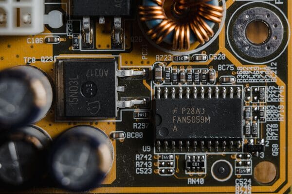
Consumer electronics get replaced every couple of years. A car's electronics are expected to run reliably for a decade or more, often in temperature swings from -40°C to 125°C or higher near the engine bay. That single fact changes almost every decision I make on a board: material choice, copper weight, via structure, component selection, and how I plan for assembly. Add in the vibration from rough roads, the humidity, and the increasingly strict quality bars set by IATF 16949 and AEC-Q100/Q200, and you can see why automotive PCB design is really its own discipline within PCB design.
The good news is that most of the pain in automotive projects is preventable. It almost always traces back to decisions made at the design stage, long before a board ever reaches an assembly line. Here's what I focus on.
1. Choose Materials for the Environment, Not Just the Schematic
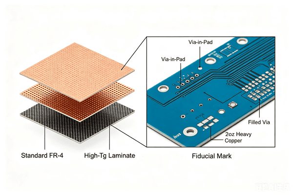
Standard FR-4 works for a lot of consumer designs, but I get nervous using it anywhere near an engine bay or in a design with aggressive thermal cycling. A few habits I've picked up:
I specify high-Tg (glass transition temperature) laminate, typically 170°C or higher, for anything exposed to sustained heat, so the board doesn't soften or delaminate during reflow or in service.
For boards near the powertrain, I lean toward materials with a CTE (coefficient of thermal expansion) that's better matched to the copper and component packages, which cuts down on solder joint fatigue over thousands of thermal cycles.
I check the laminate's moisture absorption and chemical resistance if the board will see road salt, oil mist, or coolant vapor, even indirectly.
None of this shows up as a line item on the schematic, but it shows up fast in the field if it's wrong.
2. Design With Manufacturing and Assembly in Mind From Day One
A design that looks clean in the layout tool can still be a nightmare to assemble if trace geometry, pad design, or panelization weren't considered early. I treat DFM (design for manufacturability) and DFA (design for assembly) as parallel tracks to the electrical design, not an afterthought before Gerber export.
Trace Width, Spacing, and Copper Weight
I size traces for the actual current they'll carry, including transient loads from motors, relays, and inrush current, not just steady-state values.
For power distribution near the engine or in high-vibration zones, I favor heavier copper (2oz or more) and wider traces to handle thermal cycling and reduce the chance of trace cracking.
I keep spacing well above the manufacturer's minimum wherever board real estate allows, since automotive boards often run at higher voltages and see more contamination exposure than consumer boards.
Via Design
I avoid vias directly in SMD pads unless they're properly filled and capped, since exposed via-in-pad structures are a common source of solder voiding and long-term reliability issues under thermal cycling.
For thermal vias under power components, I use an array rather than a single large via, and I confirm the fabricator's capability for via fill and plating before finalizing the pattern.
Panelization and Fiducials
I design panels with adequate rails and breakaway tabs so the assembly line can run boards through reflow and pick-and-place without excessive flex.
I always include global and local fiducials; automotive boards tend to have fine-pitch components, and skipping fiducials is a fast way to introduce placement errors at volume.
3. Plan for Thermal Management Before You Place a Single Component
Heat is the single biggest reliability threat in automotive electronics, and it's much easier to design around than to fix after the fact. I look at thermal management as part of the layout, not a post-layout patch:
I place heat-generating components (regulators, MOSFETs, drivers) with airflow and copper pour in mind, and I keep them away from heat-sensitive parts like electrolytic capacitors and crystals.
I use copper pours and thermal relief patterns tuned to the actual current path, and I add thermal vias under power packages to move heat to a ground or back-side plane.
Where the enclosure allows it, I coordinate with mechanical on heatsinks or thermal pads early, since retrofitting a heatsink onto a finished layout rarely goes well.
4. Design for Vibration and Mechanical Shock
A board that performs perfectly on the bench can fail within months once it's subjected to real-world vibration. I build in margin here rather than hoping the enclosure absorbs everything:
I keep heavy components (large electrolytic caps, connectors, transformers) close to mounting points or add mechanical support, since unsupported mass on a long lead is a classic fatigue failure point.
I avoid placing tall or heavy components right at the board edge, where flex during handling and vibration is greatest.
For connectors, I prefer through-hole or press-fit over pure SMD when the connector will see repeated mating cycles or mechanical stress, and I add strain relief in the footprint design.
I specify staking or underfill for critical BGA and connector locations when the end application has a documented vibration profile, and I flag this clearly in my assembly notes so it isn't missed on the line.
5. Get the Land Patterns and Solder Mask Right
Most of the assembly defects I've had to troubleshoot over the years trace back to footprint and solder mask decisions, not component quality. A few things I check on every automotive board before release:
I verify every land pattern against the component's actual datasheet rather than trusting a generic library footprint, especially for connectors and power packages that vary between manufacturers.
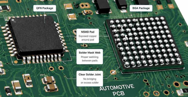
I use solder mask defined (SMD) pads carefully and stick with non-solder-mask-defined (NSMD) pads for fine-pitch parts, since NSMD generally gives more consistent solder joint formation.
I keep solder mask webbing between fine-pitch pads to prevent bridging, and I double-check paste stencil apertures for QFN and BGA packages to avoid voiding under the package.
6. Don't Forget Conformal Coating and Protective Finishes
Automotive boards frequently need conformal coating for protection against moisture, dust, and chemical exposure, and I've learned to design for it rather than bolt it on afterward:
I add keep-out zones around connectors, test points, and any component that shouldn't be coated, and I call these out clearly on the fab and assembly drawings.
I choose a surface finish (ENIG, immersion silver, or HASL depending on the application) that's compatible with both the assembly process and the coating chemistry.
I check with my assembly partner on their coating capabilities and preferred masking approach before finalizing keep-out dimensions, since this varies by process.
7. Build In Test Points and Inspection Access
Automotive quality expectations mean thorough testing at every stage, and a board that's hard to test is a board that's expensive to debug. I make sure:
Test points are accessible for ICT (in-circuit test) and functional test fixtures, and they're placed on a consistent grid where possible to simplify fixture design.
Critical nets have probe access even after conformal coating is applied, which usually means routing test points outside the coating keep-out zone.
The board supports AOI (automated optical inspection) and X-ray inspection for BGA and QFN packages, meaning no critical solder joints are hidden under other components or shielding cans without an inspection plan.
8. Document Everything the Way You'd Want to Receive It
The best automotive design in the world can still go sideways in assembly if the documentation package is incomplete. I always release a full set: Gerbers with proper layer naming, IPC-2581 or ODB++ if the fab supports it, a complete BOM with manufacturer part numbers (not just distributor SKUs), assembly drawings with polarity and orientation clearly marked, and a fabrication drawing noting stack-up, impedance requirements, and any special processes like via fill or heavy copper.
I've found that the projects with the fewest assembly questions are the ones where I spent an extra hour writing clear notes instead of assuming the assembly team would guess my intent correctly.
Choosing a Manufacturing Partner Who Understands Automotive Requirements
Even a well-designed PCB can only perform as expected when it is built by a manufacturing partner that consistently meets automotive-grade requirements. In my experience, the gap between a successful design and a reliable production board often comes down to the capabilities, processes, and quality controls of the manufacturer behind it.
That is why choosing the right automotive PCB assembly partner is just as important as getting the design itself right. A capable PCB manufacturer, such as PCBgogo, supports both prototype development and volume production, with manufacturing capabilities designed to meet the demands of automotive applications. When evaluating an automotive PCB manufacturing partner, I focus on several key factors:
Support for the material specifications I need, including high-Tg laminates, heavy copper, and controlled impedance, without a long back-and-forth to confirm capability.
A real DFM review before the board goes to fabrication, so footprint, via, and spacing issues get caught before they become assembly defects.
AOI and X-ray inspection as a standard part of the assembly process, which matters a lot for BGA and QFN-heavy automotive boards.
Quick-turn prototyping so I can validate a design change quickly, followed by a smooth transition to volume production without re-qualifying the whole process.
Responsive engineering support when a question comes up mid-build, rather than waiting days for an answer while a build sits idle.
I've sent PCBgogo everything from early-stage prototypes to production-volume automotive boards, and the combination of DFM feedback, inspection rigor, and turnaround time is exactly what this kind of work demands. If you're designing for automotive applications and want a manufacturing partner who won't make you choose between speed and quality, it's worth requesting a quote and seeing how your next board comes back.
Final Thoughts
Automotive PCB design rewards patience at the front end. Every hour I spend thinking through materials, thermal paths, vibration resistance, and assembly-friendly footprints saves me multiple hours of debugging, rework, or field failures later. The boards that make it through years of real-world abuse without a single warranty claim are never the ones that got lucky. They're the ones designed with assembly and the operating environment in mind from the very first layout decision.
I hope this checklist saves you some of the trial and error I went through to build it. And if you're ready to move a design from CAD file to working hardware, PCBgogo is a solid place to start.





