
Why is FPC Open Circuit So High? Causes & Solutions
FPC open circuit rates are often significantly higher than rigid PCBs due to dynamic stress and bending fatigue. Unlike rigid boards that suffer from static manufacturing defects (like over-etching), FPCs fail because of micro-cracks in thin rolled-annealed copper foils during repeated folding. To reduce failure rates, engineers must implement radiused corner traces, use PI stiffeners, and control soldering temperatures. High-precision AOI and Micro-CT are the industry standards for detecting these fractures.
Why FPCs Are More Prone to Failure Than Rigid PCBs?
In the world of electronics manufacturing, the transition from rigid boards to Flexible Printed Circuits (FPC) often comes with a frustrating spike in the open circuit rate. While the basic photolithography and etching processes are similar, the physical environment and material behavior are worlds apart.
The Pain Point: Higher Defect Rates
Manufacturers often find that even with a perfect manufacturing process, FPCs exhibit "latent" open circuits—meaning they pass initial electrical tests but fail during assembly or after a few days of field use. This is rarely seen in rigid boards, where a circuit is typically either functional or not from the moment it leaves the etching line.
The Root Cause: Dynamic Stress
The fundamental difference lies in Dynamic Stress. A rigid PCB is designed to stay static; its substrate (FR-4) provides a rock-solid foundation for the copper traces. In contrast, an FPC’s flexibility is its greatest asset but also its "Achilles' heel." The Polyimide (PI) substrate is incredibly thin—standard thicknesses are often 12.5μm or 25μm—meaning the copper traces must endure stretching, compression, and twisting. This mechanical movement is the primary engine behind the high FPC open circuit rate.
FPC Open Circuit vs. Rigid PCB: Key Differences
To solve the problem, we must first distinguish between a standard rigid PCB open circuit and a flexible one.
The 3 Main Culprits of FPC Open Circuit
Based on industry failure analysis, the vast majority of FPC open circuits are categorized into three distinct "killers."
1. Bending Fatigue (The "Silent Killer")
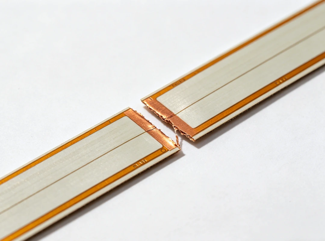
This is the number one cause of field failures. When an FPC is folded—especially in hinge areas of foldable phones or near battery connectors—the copper trace undergoes extreme tensile stress.
-
Micro-crack Propagation: It starts with a microscopic crack on the surface of the copper. With every bend, the crack deepens until the trace snaps entirely.
-
Critical Zones: Fatigue is most common where the "soft" part of the FPC meets a "hard" component, such as a connector or a stiffener. These transition zones act as stress concentration points.
2. Mechanical Damage During Manufacturing
Because FPCs are as thin as paper, they are highly susceptible to physical trauma during the production cycle:
-
Die-Cutting & Punching: If the die-cutting mold is not sharp enough or the precision is off, it can "tug" on the edge of the copper rather than cutting cleanly, leading to edge fractures.
-
Protective Film (Coverlay) Issues: FPC production requires multiple laminations. If the coverlay is misaligned or if debris is trapped, it creates a weak spot that eventually breaks under stress.
3. Thermal Stress and Assembly Strain
The heat of a soldering iron or a reflow oven can be devastating for a flexible board.
-
Substrate Shrinkage: High temperatures can cause the PI film to shrink or warp. Since the copper doesn't shrink at the same rate, this mismatch creates internal tension that snaps thin traces.
-
Over-Tight Assembly: If an FPC is designed too short and "stretched" to fit into a housing, it remains under constant tension. Over time, this constant pull leads to "creep" and eventual circuit breakage.
How to Detect FPC Open Circuits (Detection Methods)
Detecting an FPC open circuit requires a gentler touch and more advanced technology than standard PCB testing to avoid causing "secondary damage" to the fragile foils.
AOI (Automated Optical Inspection):
Using high-definition cameras and algorithms, AOI spots "near-opens"—traces that are scratched or narrowed but not yet broken. This is the first line of defense before the coverlay is applied.
Electrical Testing (E-Test):
This uses a Flying Probe or a dedicated Test Fixture.
Note: For FPCs, test needle pressure must be strictly calibrated (often below 20g-40g). Excessive pressure can puncture the thin copper foil, creating a new open circuit while trying to test for an old one.
Micro-CT Scanning:
For multi-layer FPCs where the inner layers are invisible, Micro-CT uses X-ray technology to create a 3D map of the traces. This is the gold standard for finding hidden fractures beneath the coverlay without destroying the sample.
Bending Life Test (Fatigue Test):
To ensure a design is reliable, a sample is placed in a machine that bends it thousands of times (e.g., a 180° fold at a 5mm radius) while monitoring resistance. A spike in resistance indicates a fatigue-induced open circuit.
Comprehensive Optimization: From Design to Production
To drop your FPC open circuit rate to near-zero, a multi-stage approach is required.
Optimization in Design (The Core)
-
Trace Strategy: Never use 90° or 45° angles in bending zones. Use radiused corner traces and teardrops on all pads to allow stress to flow smoothly.
-
Copper Selection: For dynamic applications, always use Rolled Annealed (RA) copper. For trace width, try to maintain ≥ 0.3mm in high-stress areas with a copper thickness of 35μm (1 oz) where possible.
-
Stiffener Design: Use PI or FR-4 stiffeners to reinforce the area where the FPC plugs into a connector, shifting the bend point away from the solder joints.
Precision Control in Production
-
High-Precision Equipment: Move away from mechanical punching and use UV Laser Cutting to ensure clean edges without mechanical burrs that lead to cracks.
-
Surface Protection: Apply Protective Film (clean-peel) throughout the entire production process to prevent "handling scratches" which are a major source of opens.
Refinement in Assembly
-
Temperature Control: Keep reflow peak temperatures below 240°C and ensure the FPC is properly pre-baked to remove moisture, preventing delamination.
-
Mechanical Slack: Design with a "slack loop." Never install an FPC in a "stretched" state; ensure there is enough length to allow for natural movement.
Why Choose PCBGOGO for Your FPC Manufacturing?
At PCBGOGO, we recognize that FPC reliability is the backbone of your product's lifespan. We have optimized our flexible circuit production line to solve the specific pain points of open circuits:
-
High-Grade Material Sourcing: We exclusively use premium RA copper and PI substrates that meet rigorous industrial standards for bending cycles.
-
Advanced Laser Processing: By utilizing state-of-the-art UV laser cutting, we eliminate the micro-fractures commonly caused by traditional mechanical die-cutting.
-
Specialized FPC E-Testing: Our flying probe testers are calibrated specifically for thin-film circuits, ensuring accurate detection without damaging the delicate copper surface.
-
Professional DFM Review: Our engineers conduct a thorough "Stress Analysis" on your design. We proactively suggest teardrop additions and trace adjustments to ensure your FPC passes the test of time.
From rapid prototyping to high-volume production, PCBGOGO provides the technical precision required to turn the "soft weakness" of FPCs into a durable, high-performance solution. We also deliver an online flexible PCB price calculator based on your board requirements.
FAQ: FPC Open Circuit & Reliability
Q1: Can an FPC open circuit be repaired?
Generally, no. Because FPCs are thin and covered in a permanent PI film (coverlay), manual soldering to "bridge" a crack is rarely reliable and usually ruins the flexibility of that area.
Q2: Does adding a stiffener increase the risk of an open circuit?
Only if it is designed poorly. A stiffener should never end abruptly in a bending zone. The transition should be gradual to prevent a "guillotine effect" on the traces.
Q3: Why is my FPC failing only after it is installed in the case?
This is usually due to "Assembly Stress." If the FPC is slightly too long or too short, the casing might be pinching it or stretching it, causing a latent fracture to finally snap.

