
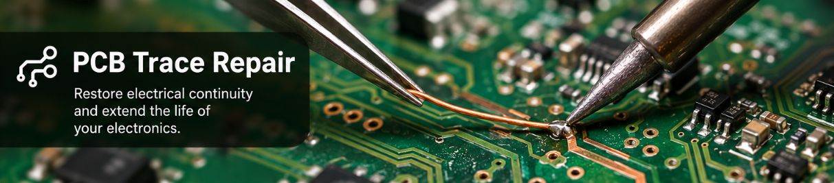
PCB Trace Repair: Complete Guide to Fixing Broken PCB Traces
A damaged PCB trace can bring an entire device to a halt, even when every component on the board is still functional. Whether the damage comes from overheating, corrosion, accidental scraping, or a failed rework attempt, a broken copper trace interrupts the electrical path that keeps a circuit operating correctly.
Knowing how to repair broken PCB traces can save time, reduce replacement costs, and extend the life of valuable electronics. This guide covers the most effective PCB trace repair methods, the tools required, common mistakes to avoid, and when repair is a better option than replacing the board.
What Is PCB Trace Repair?
PCB trace repair is the process of restoring electrical continuity to a damaged copper conductor on a printed circuit board. PCB traces function as the wiring inside the board, carrying power and signals between components.
When a trace is cracked, burnt, lifted, or corroded, the circuit can no longer operate as designed. Repairing the damaged area restores the electrical connection and allows the board to function again.
PCB trace damage commonly occurs due to:
Mechanical stress and vibration
Excessive soldering heat
Corrosion caused by moisture exposure
Overcurrent conditions
Physical damage during assembly or rework
The appropriate repair technique depends on the trace width, current requirements, and extent of the damage.
Common Types of PCB Trace Damage
Before beginning a repair, it is important to identify the type of failure. Different forms of damage require different repair methods.
| Damage Type | Typical Cause | Recommended Repair |
|---|---|---|
| Hairline Crack | Board flexing or vibration | Conductive ink or epoxy |
| Broken Trace | Physical impact or scraping | Jumper wire or repair pen |
| Burnt Trace | Excessive current | Copper wire replacement |
| Lifted Trace | Overheating during soldering | Epoxy and jumper wire |
| Corroded Trace | Moisture or contamination | Cleaning and trace reconstruction |
Correctly identifying the root cause helps prevent the same issue from occurring again after the repair.
How to Repair a Broken PCB Trace
Once the damaged area has been identified, most repairs follow a similar workflow.
Step 1: Inspect the Damage
Use a magnifier or microscope to examine the trace closely. A digital multimeter in continuity mode can confirm whether the electrical path is open.
Pay attention to nearby traces as well. Damage often extends beyond the visibly broken section.
Step 2: Clean the Area
Remove dirt, oxidation, flux residue, and any loose material from the repair area.
Isopropyl alcohol is commonly used because it evaporates quickly and leaves minimal residue. A clean surface improves solderability and ensures better adhesion for conductive materials.
Step 3: Expose Fresh Copper
Carefully scrape away the solder mask on both sides of the damaged trace using a precision knife or fiberglass pen.
Exposing fresh copper provides a reliable connection point for the repair.
Step 4: Choose the Appropriate Repair Method
The best repair method depends on the size of the break and the electrical demands of the circuit.
The following sections explain the most common techniques.
How to Use a PCB Trace Repair Pen
For small cracks and low current applications, a pcb trace repair pen can provide a quick solution.
These pens contain conductive silver ink that restores continuity across a damaged section.
1. Shake the pen thoroughly.
2. Clean the damaged area.
3. Apply conductive ink across the break.
4. Allow the ink to cure according to the manufacturer’s instructions.
5. Test continuity with a multimeter.
6. Apply a protective coating if needed.
This method works well for consumer electronics, remote controls, membrane circuits, and prototype boards.
However, conductive ink generally has higher resistance than copper and may not be suitable for high current traces.
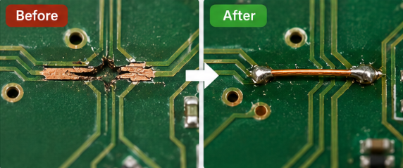
Repairing PCB Traces with Jumper Wire
For larger breaks, jumper wire repair is often the most reliable option.
Instead of recreating the missing copper section, a small insulated wire bridges the damaged area and creates a new conductive path.
Many technicians prefer 30 AWG wire wrap wire or fine magnet wire because they are easy to route and solder.
Advantages of Jumper Wire Repair:
Excellent conductivity
Suitable for high current applications
Strong long term reliability
Low repair cost
This approach is commonly used in industrial equipment, automotive electronics, and prototype development.
Using Conductive Epoxy for PCB Board Trace Repair
Some assemblies contain heat sensitive components that make soldering risky.
In these situations, conductive epoxy offers an alternative repair method.
Conductive epoxy combines adhesive strength with electrical conductivity. Once cured, it forms a permanent bond between the damaged trace sections.
Although the curing process takes longer than soldering, conductive epoxy can be useful when thermal exposure must be minimized.
PCB Trace Repair Methods Compared
Choosing the right technique depends on the application.

For most professional repairs, jumper wire remains the preferred solution when durability is the primary concern.
Common Mistakes That Cause Repair Failure
Even experienced technicians occasionally encounter repair failures. Most issues can be traced back to a few common mistakes.
1. Applying Excessive Heat
Too much heat can lift nearby traces and damage pads, creating additional repair work.
2. Skipping Surface Preparation
Oxidized copper and contamination prevent proper bonding. Cleaning should never be skipped.
3. Using Conductive Ink for High Current Traces
While convenient, conductive ink cannot always handle the current levels supported by the original copper trace.
4. Failing to Protect the Repair
Exposed conductive material can corrode over time. A protective coating significantly improves long term reliability.
Testing the Repair
Before powering the board, verify that the repair is electrically and mechanically sound.
Use the following checklist:
1. Confirm continuity across the repaired section.
2. Check for shorts to adjacent traces.
3. Verify mechanical stability.
4. Inspect solder joints under magnification.
5. Apply power and perform functional testing.
Thorough testing helps prevent intermittent failures that can be difficult to diagnose later.
When Should You Repair Instead of Replace?
Not every damaged PCB should be repaired.
Repair is often the best choice when:
The board is expensive to replace.
Replacement lead times are long.
The damaged area is limited to a few traces.
The product is obsolete.
If multiple internal layers are damaged or extensive burn damage is present, replacement may be more cost effective.
Once you’ve determined that a board requires replacement rather than repair, having accurate manufacturing files becomes the next priority. If you’re preparing a new fabrication order, PCBgogo supports PCB fabrication and assembly services and offers an online quoting system that can simplify the transition from repair evaluation to production.
FAQ
How do you repair broken PCB traces?
The most common methods include conductive ink, conductive epoxy, jumper wire, and copper foil patches. The best choice depends on the size of the break and the current carried by the trace.
Does a PCB trace repair pen really work?
Yes. A pcb trace repair pen can effectively restore continuity across small breaks and cracks. It is most suitable for low current applications.
What causes PCB traces to break?
Common causes include overheating, mechanical stress, corrosion, accidental scraping during rework, and excessive current flow.
Can burnt PCB traces be repaired?
Yes. Burnt sections can often be removed and replaced with jumper wire or copper foil. The replacement conductor should be sized appropriately for the required current.
What is the best wire for PCB trace repair?
Many technicians use 30 AWG wire wrap wire or fine magnet wire because they are easy to solder and route across the board.
How do I protect a repaired PCB trace?
Apply UV solder mask, conformal coating, or another insulating protective layer after testing. This helps prevent corrosion and accidental short circuits.
Conclusion
PCB trace repair is a valuable skill that can restore functionality to damaged electronics and reduce unnecessary board replacements. By selecting the right repair method, preparing the surface correctly, and thoroughly testing the result, you can achieve repairs that remain reliable for years. When repair is no longer practical, a professionally manufactured replacement board is often the most efficient next step.


