
PCB Board Parts: The Complete Guide to Components on a PCB
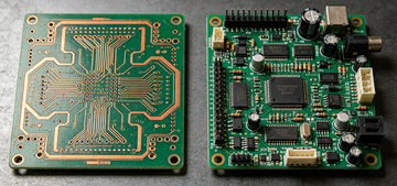
Order a PCB and you get a bare board — copper, solder mask, silkscreen, nothing that actually does anything yet. The parts are what turn that board into a working circuit, and getting them right is where most first-run assembly problems actually start, not in the fabrication itself.
What Are PCB Board Parts?
PCB board parts are the physical components soldered or inserted onto a printed circuit board that give it a working function — everything from a $0.01 resistor to a multi-core processor. "PCB board parts", "electronic components PCB", and "components on a PCB" all describe the same thing: the devices populating the board, not the bare board itself.
Passive components — resistors, capacitors, inductors. They shape or store electrical energy but don't need power to operate.
Active components — transistors, diodes, integrated circuits. They need power to function and can switch, amplify, or process a signal.
The board itself isn't a "part" — copper traces, vias, solder mask, and silkscreen are the host structure that lets parts connect and stay in place.
The Core PCB Board Parts You'll Find on Almost Every Board
Most boards, regardless of application, draw from the same short list of core part types. Here's what each one does and how it's labeled on the silkscreen.
| Component | Refdes | Function | Typical Rating |
|---|---|---|---|
| Resistor | R | Limits current, sets voltage dividers | 1Ω – several MΩ |
| Capacitor | C | Stores charge, filters noise, decouples power rails | pF – several thousand μF |
| Inductor | L | Stores energy in a magnetic field, filters switching noise | nH – several mH |
| Diode | D | Passes current in one direction only | Forward voltage 0.2–0.7V typical |
| Transistor / MOSFET | Q | Switches or amplifies a signal | mA to tens of amps |
| Integrated circuit | U / IC | Packaged function — processing, regulation, interface | Pin count 3 to 1000+ |
| Connector | J | Interfaces the board to cables or other boards | Current rating 1A–10A typical |
| Switch / Relay | SW / K | Manual or electrically driven contact switching | Contact rating varies widely |
| Crystal / resonator | Y / X | Provides a stable clock frequency for ICs | kHz to tens of MHz |
Advantages of Choosing the Right PCB Board Parts
Getting component selection right pays off well beyond the schematic stage.
Reliable operation — a part rated with the correct voltage, current, and temperature margin is far less likely to be the reason a board fails in the field.
Compact, efficient layouts — the right package size lets a design hit its footprint target without fighting for board space.
Lower cost at scale — standard, multi-sourced parts avoid the price spikes that come with single-source or near-obsolete components.
Easier repair and test — parts with clear polarity marking and accessible footprints are faster to diagnose and swap during rework or field service.
Key Characteristics That Define a PCB Board Part
Beyond function, four characteristics decide whether a part actually works in your design:
Package and footprint — e.g. a 0402 resistor (1.0mm × 0.5mm) versus a 1206 (3.2mm × 1.6mm); smaller saves space but raises placement and rework difficulty.
Mounting method — through-hole (THT) or surface-mount (SMT); this decides how the part is soldered and how much board space it needs.
Electrical rating — voltage, current, power, and temperature rating, ideally with margin above your circuit's real operating conditions.
Reference designator — the silkscreen label (R1, C5, U3) that ties the physical part back to its line in the schematic and BOM.
How PCB Board Parts Are Mounted: THT vs SMT
Nearly every part on the table above can come in either a through-hole or surface-mount version, and the mounting method changes how it's soldered, how much space it needs, and how it holds up mechanically.
| Feature | THT (Through-Hole) | SMT (Surface-Mount) |
|---|---|---|
| Mounting | Leads through drilled holes | Pads on the board surface |
| Joint strength | High — mechanically anchored | Lower — adhesion is surface-only |
| Board density | Lower — needs hole + lead clearance | Higher — parts sit closer together |
| Typical parts | Connectors, power components, high-vibration parts | Resistors, capacitors, ICs, high-density logic |
| Rework | Simple — desolder with an iron | Harder — needs hot air or reflow rework |
How to Identify PCB Board Parts on a Real Board
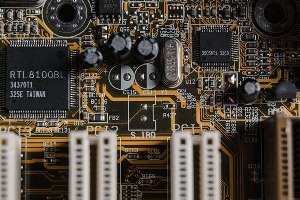
Staring at a populated board with no BOM in hand, the reference designator is the fastest way in.
Find the refdes printed on the silkscreen (R14, C22, U3) — the letter tells you the category, the number is unique to that board.
Check polarity markers — a stripe on a diode marks the cathode, a shorter pad or “–” marks an electrolytic capacitor's negative lead, a dot or notch marks IC pin 1.
Match the footprint to the BOM — confirm the physical package (0603, SOT-23, QFN) matches what's specified, not just the value.
Read the top-mark code on ICs and diodes and cross-reference it against the manufacturer's part number when the silkscreen alone isn't enough.
What Causes Component Selection Mistakes to Delay a PCB Order
Most delays between BOM submission and finished boards trace back to a handful of repeat issues:
Footprint mismatch — the BOM specifies one package size but the layout was built around another, so the part physically doesn't fit the pad.
Ambiguous refdes-to-BOM mapping — duplicate or missing reference designators mean the wrong part gets placed at the wrong position.
Underrated components — a part specified without voltage or temperature margin can pass initial test and still fail early in the field.
Obsolete or single-source parts — a part with no second source or an approaching end-of-life date can stall a production run for weeks while a substitute gets qualified.
None of these show up by reading the schematic alone — they show up when the BOM gets checked against the actual footprint and stock status before parts are ordered.
Getting Your BOM and Board Parts Right the First Time
A wrong footprint or a missing reference designator is cheap to fix at the BOM review stage and expensive to fix after boards are already populated. The difference between a smooth first-run build and a respin usually comes down to whether someone checked the parts against the actual layout before assembly started.
This is where PCBgogo becomes relevant. PCBgogo cross-checks your BOM against footprints, stock availability, and DFM rules before a single component gets placed, and can source parts directly when a line item is hard to find. The result is fewer mid-build holds, fewer respins, and a shorter path from BOM upload to a finished, working board.
Frequently Asked Questions
What's the difference between PCB parts and PCB components?
None — PCB parts, PCB components and components on a PCB all refer to the same thing: the physical devices soldered onto the board, as opposed to the bare board itself (copper, solder mask, silkscreen).
How do I identify an unlabeled PCB board part?
Match its package shape and pin count to a common footprint (SOT-23, 0603, SOIC), then cross-reference the printed top-mark code against a component datasheet search — the reference designator on the silkscreen narrows the category first.


