
How to Desolder SMD Components with a Soldering Iron on a PCB
- how to desolder smd components with soldering iron
- smd components
- smd electronic components
- soldering smd components
- smd resistor
- smd resistor code
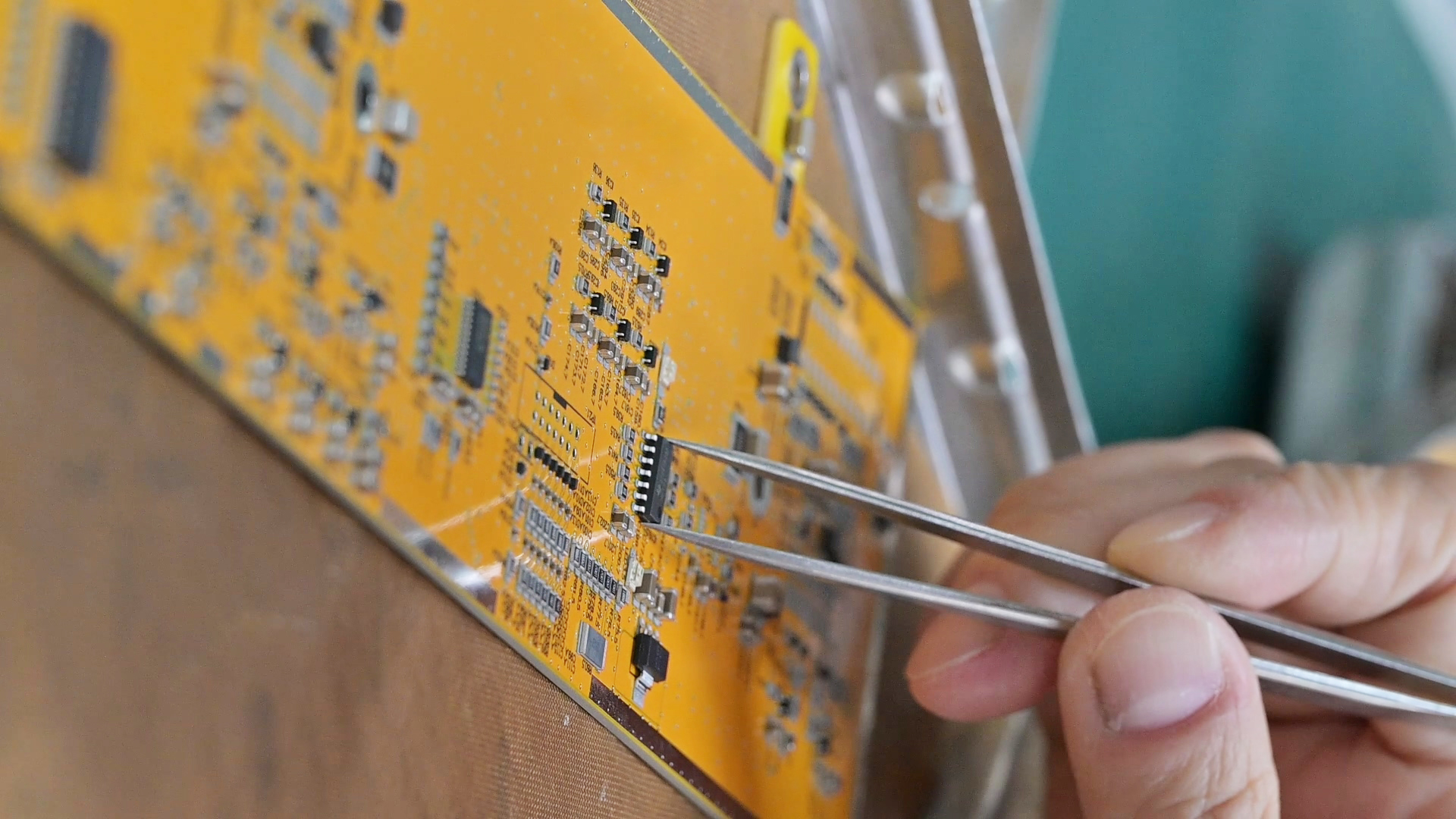
Anyone who has ever used a soldering iron to remove SMD components has probably had this experience: if your hand slips even slightly, the pads can lift off, and the entire board you worked on might be ruined. While hot air rework stations are standard equipment in factory repair work, the truth is that most engineers and electronics hobbyists only have a basic soldering iron on their workbench.
But with the right technique, you can still get the job done successfully. It breaks down practical, step-by-step instructions and removes all unnecessary details, leaving only the useful tips that help you remove SMD components cleanly without causing damage.
Now, let’s take a look.
What You Need Before You Start
In practice, SMD rework doesn't require expensive equipment. However, using the right tools can significantly improve control and consistency during the process. This is especially true when working on high-density boards—if you're dealing with tightly packed layouts typical of advanced PCB designs like HDI boards, precise tool control becomes even more critical.
Fine-tip soldering iron (0.5–1 mm chisel or conical tip), temperature-controlled, set to 320–360°C
Flux pen or liquid flux — this is non-negotiable; flux makes solder flow and prevents pad damage
Solder wick (desoldering braid), 1.5–2 mm width for most SMD work
Tweezers (anti-static, fine-point)
Isopropyl alcohol (90%+) and a brush for cleanup
Magnifying glass or digital microscope — especially useful for 0402 and smaller packages
Optional but helpful: a small vise or PCB holder to keep your hands free.
How to Desolder SMD Components with a Soldering Iron
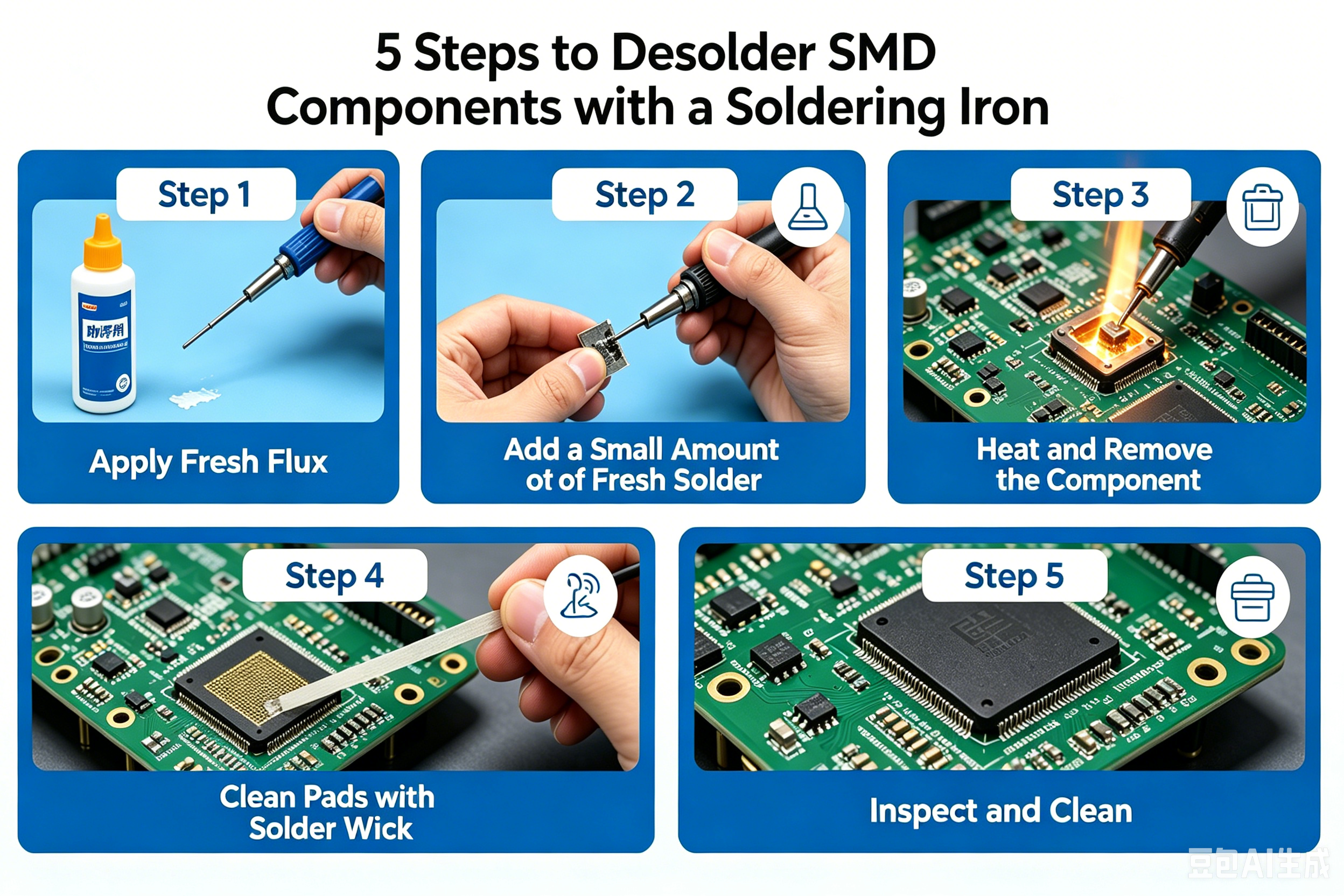
Step 1: Apply Fresh Flux
Before you touch iron to pad, apply flux. Flux lowers the melting point of the existing solder, prevents oxidation, and helps the solder flow off the pad rather than bridge across leads. Skip this and you'll be fighting the iron the whole time.
For most SMD components—resistors, capacitors, small ICs—a quick swipe from a flux pen is enough. For dense packages like QFPs, apply liquid flux generously around all pins.
Step 2: Add a Small Amount of Fresh Solder
This sounds counterintuitive, but adding a tiny bead of fresh solder to each joint before removing the component improves thermal transfer and lowers the melting temperature of the existing joint. The new solder mixes with the old, making the whole joint fluid faster and reducing the time your iron sits on the pad.
Step 3: Heat and Remove the Component
For two-pad components (resistors, capacitors, diodes): Touch the iron to one pad and heat for 2–3 seconds until the solder flows. While holding the component lightly with tweezers, quickly slide the iron to the second pad. Once both sides are molten simultaneously, lift the component straight up. The goal is total contact time under 5 seconds per attempt—excessive heat lifts copper pads.
If you can't get both pads liquid at once, try the "drag" method: apply flux, add a small solder bridge connecting both pads, then heat the bridge so both joints reflow together.
For multi-lead packages (SOICs, SOTs): Work one row at a time. Drag the iron tip along all pins with a light touch—don't press—letting the solder wick from pin to pin. Use braid between passes to remove excess. This takes a few passes; don't rush it.
For flexible PCBs, be more careful with heat. Even though the material can handle high temperatures, the copper layer is easier to damage if overheated, so keep heating time shorter and work more gently.
Step 4: Clean the Pads with Solder Wick
Once the component is off, you'll have solder residue on the pads. Place solder wick flat on the pad, set the iron on top of the wick, and wait for the solder to flow up into the braid—usually 2–4 seconds. Lift the wick and iron together; don't drag. Repeat until the pads are clean and flat.
Avoid holding the iron on the wick too long. Overheated braid won't absorb solder and can scorch the pad.
Step 5: Inspect and Clean
Use a magnifying glass to confirm the pads are clean, flat, and still firmly bonded to the board. Any lifted corner or delamination means you pushed too hard or applied too much heat. Clean the area with IPA and a brush to remove flux residue, which can cause corrosion or leakage currents over time.
Reading SMD Resistor Codes Before You Replace a Component
Before you solder in a replacement, verify you have the right part. SMD resistors use a numeric marking system that trips up a lot of people.
3-digit code (e.g., 472): The first two digits are significant figures, the third is the multiplier (number of zeros). So 472 = 47 × 102 = 4,700Ω.
4-digit code (e.g., 4702): First three digits are significant figures, fourth is the multiplier. 4702 = 470 × 102 = 47,000Ω.
EIA-96 code (e.g., 01C): Used on 1% precision resistors. The two-digit number indexes into the EIA-96 table; the letter defines the multiplier. 01C = 100 × 102 = 10,000Ω.
If your SMD resistor code reads "000" or "0000," that's a jumper (zero-ohm resistor)—a common placeholder used for routing flexibility or board configuration.
Always double-check the SMD resistor code against your BOM before installing a replacement. An 0402 package looks identical whether it's 100Ω or 100kΩ.
Common Mistakes That Damage Pads
1. Too much heat, too long. Copper pads bond to the substrate with adhesive. Prolonged heat—more than 5–6 seconds per joint—breaks that bond. Set your iron temperature correctly and work quickly.
2. Skipping flux. Dry solder won't flow cleanly. Flux is the difference between a component that lifts in 3 seconds and one that requires 10 seconds of iron time.
3. Pulling before both pads are liquid. Forcing a component off while one pad is still solid rips the pad off with it. Patience here pays off.
4. Pressing the iron down. The iron transfers heat through contact, not pressure. Pressing harder doesn't heat faster—it deforms the tip and increases the risk of slipping.
Getting Your Reworked Board Back Into Service
Once you've replaced the component and cleaned the pads, do a quick visual inspection under magnification before powering the board. Check for:
Solder bridges between adjacent pads
Cold joints (dull, grainy appearance)
Lifted pads or torn traces
Any residual flux that could cause issues in high-impedance circuits
If you're working on prototype or low-volume boards and want to avoid this headache entirely, getting the assembly right the first time is worth the investment. At PCBgogo, their PCBA service handles SMD component placement with machine precision—your BOM and Gerber files drive automated pick-and-place, which dramatically reduces the rework rate that makes hand desoldering necessary in the first place. For engineers moving from prototype to small-batch production, that transition from bench soldering to professional SMT assembly is where yield starts to matter.
Quick Summary
Desoldering SMD components with a soldering iron comes down to four non-negotiables: use flux every time, add fresh solder to improve thermal transfer, keep iron contact time under 5 seconds per joint, and clean up with solder wick before inspecting. Whether you're swapping a labeled SMD resistor or removing a multi-pin SOIC, the same principles apply—heat fast, lift clean, and verify the pads before you move on.
The best rework is the rework you never have to do. If you're scaling from prototype to production, PCBgogo's PCBA service uses automated pick-and-place driven by your BOM and Gerber files—so the components go on right the first time, and hand desoldering stays off your to-do list.
FAQ
Q: Can I desolder SMD components without hot air?
Yes, for most packages—resistors, capacitors, diodes, SOICs, SOTs. A fine-tip iron with flux and solder wick covers the majority of rework. QFNs and BGAs are the exception; those genuinely need hot air.
Q: What temperature should I use?
320–340°C for lead-free solder (SAC305); 280–300°C for leaded. Go up to 360°C if joints aren't flowing, but stay under 380°C to avoid lifting pads.
Q: How do I read an SMD resistor code on a tiny component?
Use a USB microscope or loupe to see the marking, then decode it: 3-digit (472 = 4,700Ω), 4-digit (4702 = 47,000Ω), or EIA-96 for 1% precision resistors. Details are in the SMD resistor code section above.
Q: Why does my solder wick not absorb solder?
Usually oxidized braid or no flux. Add flux to both the pad and the wick before applying heat—it makes a significant difference.
Q: How many rework cycles can a pad handle?
Typically 3–5 careful cycles before copper adhesion degrades. Keep iron time short on each pass to preserve as many cycles as possible.
Q: What's the difference between SMD and through-hole components?
SMD electronic components mount on the board surface; through-hole leads pass through drilled holes. SMD dominates modern designs for its smaller footprint and automated assembly compatibility. Desoldering methods differ—SMD rework is single-side, through-hole requires clearing the hole from below.


