
Castellated Holes vs. Through-Holes: Which PCB Design Should You Choose?
The choice between Castellated Holes and standard Through-Holes depends on your assembly method. Through-holes are fully enclosed within the board, offering high mechanical strength for traditional components. Conversely, Castellated Holes (half-holes) are plated notches on the PCB edge, allowing one board to be soldered onto another like an SMD component. Use Castellated Holes for modular, space-saving designs (IoT/RF modules) and Through-holes for power-heavy or cost-sensitive industrial applications.
What are Castellated Holes and Through-Holes, and Why Use Them?
Understanding the physical structure and strategic advantages of these two connection types is the first step in optimizing your PCB layout.
Standard Through-Hole PCB (PTH)
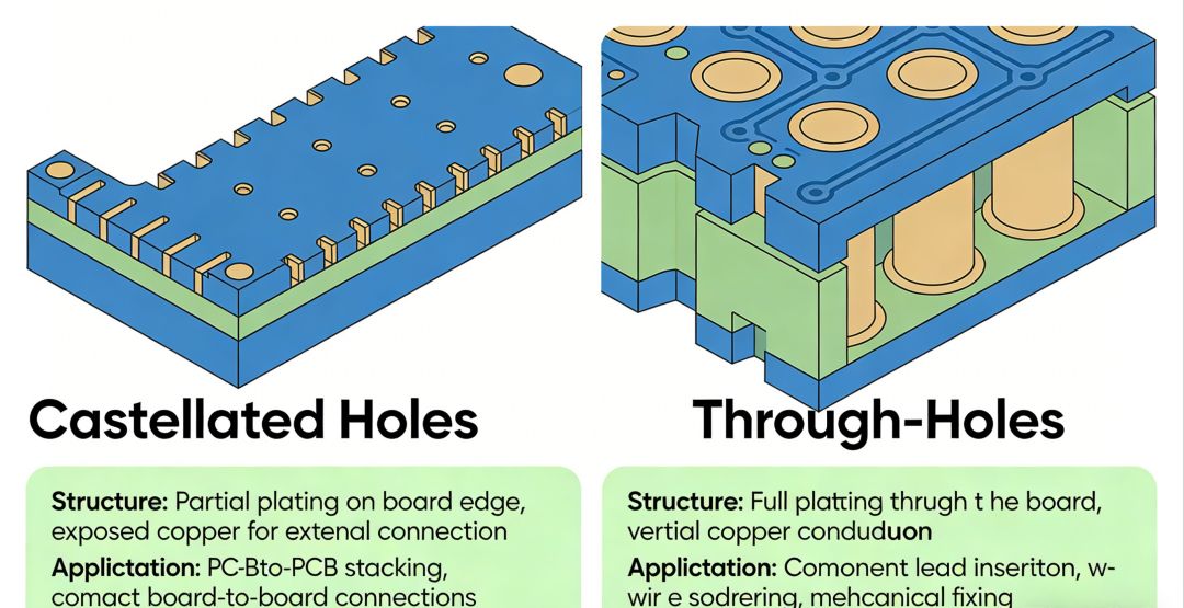
The Structure: Plated Through-Holes (PTH) are copper-lined holes drilled completely through the PCB substrate, surrounded by a full circular or square pad.
Why Use Them? They offer superior mechanical bond strength, making them ideal for connectors or heavy components that experience physical stress. Additionally, they are the most cost-effective solution for double-sided boards and are highly tolerant of manual soldering and rework.
Castellated Holes (Half-Holes)
The Structure: These are essentially standard plated holes that have been precisely cut in half during the edge-routing process. This creates a series of U-shaped, copper-plated "notches" along the board’s perimeter.
Why Use Them? They enable modular PCB design. By using Castellated Holes, a daughterboard can be mounted flat against a carrier board using standard Surface Mount Technology (SMT). This is the gold standard for creating compact Wi-Fi, Bluetooth, or ESP32 modules where vertical space is at a premium.
4 Key Design Differences between Castellated Holes and Through-Holes
Designing for Castellated Holes requires tighter tolerances and a different mindset regarding pad geometry and board stability.
A. Alignment and Edge Relationship
In a standard board, hole placement has a generous margin. For Castellated Holes, the hole center must lie exactly on the board's outline. Any deviation during fabrication can lead to "burrs" or incomplete copper plating.
B. Pad Diameter and Extension
Standard pads are typically 1.3 to 1.8 times the hole diameter. For Castellated Holes, you must enlarge the pads. Critically, the copper pad must overhang the edge to ensure the copper does not peel off during the mechanical routing process.
C. Pitch and Minimum Spacing
To prevent solder bridging during reflow, the pitch between two holes should be generous. Crowding these notches makes the board edge fragile and complicates the high-density PCB assembly process.
D. Mechanical Rigidity
Removing material from the edge naturally weakens the PCB. Consider increasing the board thickness (e.g., from 1.0mm to 1.2mm) to prevent warping during thermal cycling in the soldering oven.
Manufacturing Process: Why Castellated Holes Cost More?
The production of Castellated Holes is more complex than standard PTH, involving several specialized steps:
Precision CNC Routing: Standard boards use V-scoring for separation, but V-scoring shreds the copper inside a half-hole. Instead, we must use slow, high-precision CNC milling to cut through the plated copper, ensuring a clean "half-moon" finish.
Specialized Plating Cycles: To ensure the copper doesn't peel off when cut, the holes undergo a specialized chemical plating process to increase the bond strength between the copper and the FR4 epoxy resin.
Advanced Deburring: Cutting through metal and fiberglass simultaneously creates burrs. Every board must undergo a microscopic deburring process to remove tiny copper slivers that could cause electrical shorts.
A-Class Inspection: We perform 100% optical inspection on the hole walls to verify that the plating is uniform and that no "lifting pads" occurred during the routing stage.
Application Scenarios: Which One is Best for You?
Choose Through-Hole If: You are designing high-voltage power supplies, heavy-duty industrial sensors, or educational kits. If your design has plenty of space and requires high physical durability, the Through-Hole is the most reliable and affordable choice.
Choose Castellated Holes If: You are building IoT modules, Wi-Fi/Bluetooth adapters, or wearable technology. If your goal is miniaturization and you want your PCB to be surface-mounted onto another board like a high-density component, Castellated Holes are essential.
Why Choose PCBGOGO for Your Castellated Hole Design?
Manufacturing high-quality Castellated Holes requires a partner who understands the nuances of edge plating. PCBGOGO provides professional solutions:
High-Precision CNC Routing: We ensure clean cuts with zero burrs, protecting your signal integrity.
Advanced DFM Support: Our engineers review your half-hole dimensions to ensure they meet manufacturing tolerances.
Quality Assurance: Every board undergoes AOI and rigorous edge-connectivity testing.
Fast Lead Times: We offer competitive turnaround for complex modular designs without sacrificing quality.
Summary
While standard through-holes remain the reliable choice for most general electronics, Castellated Holes are essential for the modern era of modular PCB design. By understanding the design specifications and manufacturing challenges of half-holes, you can successfully create compact, plug-and-play modules that are ready for high-volume SMT assembly.
FAQs
Q: Are Castellated Holes more expensive than standard PCBs?
A: Yes, typically by 10-20% due to the specialized CNC milling and deburring processes required to ensure clean edge plating.
Q: Can I use V-scoring for a board with Castellated Holes?
A: No. V-scoring will likely damage the copper plating inside the hole. CNC routing is mandatory for a professional finish.
Q: What is the recommended minimum hole size?
A: For reliable plating and routing, a minimum diameter of 0.5mm to 0.6mm is generally recommended by most PCB manufacturers.
Q: Can these holes be soldered by hand?
A: Yes, though they are optimized for reflow ovens. If hand-soldering, use a fine tip and high-quality flux to ensure the solder wicks properly into the U-shaped notch.

