
 日本語
日本語
 한국어
한국어

220 Ohm Resistor: Color Code, LED Use and PCB Selection
QUICK ANSWER A 220 ohm resistor is a passive component with a nominal resistance of 220Ω. It opposes current flow and converts electrical energy into heat. By Ohm's law, I = V / 220, where V is the voltage across the resistor. For example, 1V across it produces approximately 4.55mA.
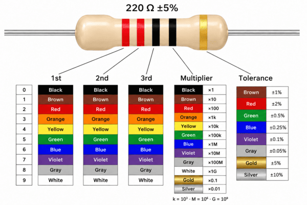
A 220 ohm resistor has a nominal resistance of 220Ω, also written as 220R or 0.22kΩ. Its common four-band color code is red–red–brown–gold, indicating ±5% tolerance. On an SMD resistor using a three-digit numeric code, 221 means 220Ω.
You will often find this value in LED indicator circuits and electronics starter kits. Before using one, check more than the resistance: the supply voltage, LED current, resistor wattage and package all affect whether it fits your circuit.
| Quick identification | Meaning |
|---|---|
| Four bands: red–red–brown–gold | 220Ω, ±5% |
| Five bands: red–red–black–black–brown | 220Ω, ±1% |
| Three-digit SMD marking: 221 | 22 × 101 = 220Ω |
| Four-digit SMD marking: 2200 | 220 × 10? = 220Ω |
| Three-digit SMD marking: 220 | 22Ω, not 220Ω |
How to Read the 220 Ohm Resistor Color Code
For a four-band resistor, the first two bands give the digits, the third gives the multiplier, and the fourth shows tolerance.
Read red–red–brown–gold as follows:
Red: 2.
Red: 2, making 22.
Brown: multiply by 10.
Gold: ±5% tolerance.
The result is 22 × 10 = 220Ω. At the specified reference conditions, the tolerance range is 209–231Ω; a reading of 218Ω is therefore consistent with this specification, allowing for meter uncertainty.
A five-band resistor adds a third significant digit. Red–red–black–black–brown reads as 220 × 1, with ±1% tolerance, giving 217.8–222.2Ω. A five-band version ending in gold still has ±5% tolerance. The number of bands alone does not determine accuracy.
Start from the end opposite the tolerance band. Gold or silver at one end usually makes the direction easy to identify; if the markings are unclear, verify the value with a meter.
Also check the multiplier carefully. In four-band codes, red–red–black is 22Ω, while red–red–red is 2.2kΩ. One different band changes the resistance by a factor of ten.
What Is the SMD Code for a 220Ω Resistor?
The common three-digit code is 221: the first two digits are 22, and the final digit means multiply by 101.
In a four-digit numeric system, 2200 gives 220 × 10?. However, 220 in the three-digit system means 22 × 10?, or 22Ω. Treating a printed "220" as 220Ω can produce a substantial current error.
Some precision parts use an EIA-96 code, and small packages may have no marking at all. Confirm the manufacturer's marking scheme and reel label rather than assuming every 220Ω chip says "221."
Package codes describe physical size, not resistance. A 0603 resistor can have many different resistance values. For a broader explanation of package dimensions and marking systems, see PCBgogo's SMD resistor guide.
Is a 220 Ohm Resistor Enough for an LED?
It can be suitable for a low-voltage indicator LED, but calculate the current first. A resistor does not deliver a fixed current regardless of the circuit around it.
For one LED connected in series with a resistor:
I = (V_S ? V_F) / R
Here, V_S is the voltage applied to the series combination, V_F is the LED's forward voltage at its operating current, and R is the resistance. Use volts and ohms to obtain current in amperes.
For a 5V supply and an assumed 2.0V LED forward voltage:
I = (5 ? 2) / 220 ≈ 0.0136A = 13.6mA
The LED takes approximately 2V, leaving 3V across the resistor. Dividing the entire 5V by 220Ω would ignore the LED's voltage drop.
These calculated examples show why the supply and LED matter:
| Applied voltage | Assumed LED forward voltage | Current through 220Ω | Resistor dissipation |
|---|---|---|---|
| 3.3V | 2.0V | 5.9mA | 7.7mW |
| 5.0V | 2.0V | 13.6mA | 40.9mW |
| 5.0V | 3.0V | 9.1mA | 18.2mW |
These are estimates, not bench measurements. LED forward voltage varies with current, temperature and the individual device. Check its datasheet and compare the result with the intended operating current.
Check GPIO Limits and Tolerances
When a GPIO on an Arduino board or another microcontroller drives the LED, its loaded output voltage may differ from the supply rail. Check the microcontroller's output characteristics, per-pin limits and combined port limits. An absolute maximum rating is not a normal operating target.
For an illustrative tolerance check, assume the supply can reach 5.25V, the LED forward voltage can fall to 1.8V, and the 220Ω resistor has ±5% tolerance. Its minimum resistance is 209Ω:
I_max ≈ (5.25 ? 1.8) / 209 = 16.5mA
That is higher than the nominal 13.6mA estimate. If your LED or output pin needs less current, increase the resistance or use an appropriate driver.
220Ω vs. 330Ω vs. 470Ω
With the same 5V supply and assumed 2V LED drop, 220Ω gives approximately 13.6mA, 330Ω gives 9.1mA, and 470Ω gives 6.4mA.
A higher resistance reduces current and will usually reduce brightness. Many indicator applications need only a few milliamps, so choose the current that provides useful visibility within the device limits. For separate parallel LED branches, give each branch its own resistor to help control current sharing.
What Power Rating Do You Need?
Calculate the heat dissipated in the resistor using:
P = I2R = V_R2 / R
V_R is the voltage across the resistor itself. In the 5V, 2V LED example, P = 32 / 220 ≈ 0.041W. A 1/4W resistor provides useful nominal headroom for this case, provided the operating conditions meet its datasheet requirements.
Do not choose wattage from resistance alone. Connecting 220Ω directly across 12V produces 122 / 220 ≈ 0.655W, exceeding both 1/4W and 1/2W ratings.
Also inspect temperature derating, maximum working voltage and pulse ratings. A hot enclosure or repeated surge can make a resistor unsuitable even when the room-temperature, steady-state calculation looks acceptable. Package size alone does not guarantee wattage; different series can offer different power ratings in the same footprint.
Other Uses for a 220Ω Resistor
Two 220Ω resistors can form a voltage divider. Across 5V, their midpoint is approximately 2.5V with no load, while the pair draws 5 / 440 = 11.4mA continuously. That current can be significant in a battery-powered design, where higher resistance values may be preferable.
Connecting a load changes the divider's output voltage, so this arrangement is not a replacement for a regulated sensor supply. A 220Ω resistor can also form part of an RC filter or transistor base circuit, but select it from the required filter response or base current. Its usefulness in an LED tutorial does not make it a default value for those jobs.
How to Check a 220 Ohm Resistor with a Multimeter
Disconnect power and discharge stored energy before measuring resistance. Set the meter to Ω mode, then place one probe on each resistor terminal. Resistors have no polarity, so either probe orientation works.
Compare the reading with the part's tolerance range and your meter's accuracy. A ±5% part need not read exactly 220Ω.
If an installed resistor reads much lower than expected, other components may provide parallel current paths. Lift one terminal or remove the component to isolate it before deciding it is faulty. Unstable readings can also come from poor probe contact or contaminated leads.
Choosing a 220Ω Resistor for PCB Assembly
An axial through-hole part is convenient for breadboards and manual prototypes. Surface-mount parts suit compact layouts and automated assembly. Choose a package that satisfies the electrical requirements and leaves enough room for inspection or rework.
For PCB sourcing, specify a complete component rather than "220 ohm resistor." A useful BOM description is:
R7 — 220Ω, ±1%, 0.125W, 0805 imperial (2012 metric), thick-film resistor, with the selected manufacturer part number.
This is an example specification, not a recommendation for every circuit. Confirm the actual part's ratings, dimensions and footprint before ordering. State whether size codes are imperial or metric to avoid ambiguity.
Before releasing the assembly files, check:
The schematic value matches the BOM and manufacturer part number.
The footprint matches the selected package.
Worst-case current and dissipation meet the circuit requirements.
Approved substitutes preserve the required tolerance, power and voltage ratings.
Keep reference designators consistent across the BOM, placement data and assembly drawing. PCBgogo's files requested for PCBA explains the documents needed to turn those component choices into an assembly order.
Frequently Asked Questions
What Can I Use Instead of a 220 Ohm Resistor?
For a simple LED indicator, 330Ω or 470Ω may work if the lower current still provides enough brightness. Two resistors of 100Ω and 120Ω in series give a nominal 220Ω; check each one's dissipation. In timing, feedback or measurement circuits, evaluate the effect of changing resistance before substituting another value.
Is 220Ω the Same as 220kΩ?
No. 220Ω equals 0.22kΩ. A 220kΩ resistor is 220,000Ω, or 1,000 times larger.
Can I Use a 220Ω Resistor for an LED on 12V?
With an assumed 2V LED drop, the current would be about 45.5mA and resistor dissipation about 0.455W. For a 10mA target under those assumptions, calculate R = (12 ? 2) / 0.01 = 1kΩ, then verify tolerance and temperature limits.
Does a 220 Ohm Resistor Have a Positive Side?
No. An ordinary fixed resistor is nonpolarized. In a simple series LED circuit, it can go on either side of the LED; the LED itself must have the correct orientation.





