日本語
 한국어

What is a 10k Ohm Resistor? PCB Uses and Troubleshooting
QUICK ANSWER A 10k resistor has a nominal resistance of 10,000 ohms. On a PCB, it commonly biases analog nodes, limits small currents, sets RC timing, and holds digital inputs at a known logic level. The correct tolerance, power rating, package, and circuit position matter as much as the resistance value.
A board can pass a quick bench test and still fail in the field because a reset pin floats, an I2C edge rises too slowly, or a USB control net uses a familiar value in the wrong place. The 10k resistor is common enough to be chosen by habit, so the useful question is when 10 kΩ is electrically justified.
What Is a 10k Ohm Resistor
A 10k ohm resistor presents 10,000 Ω of resistance at its specified test conditions. Ohm's law gives the first design check: at 3.3 V, an ideal 10k resistor carries 0.33 mA and dissipates about 1.09 mW; at 5 V, it carries 0.5 mA and dissipates 2.5 mW. Those figures are far below a typical 0.1 W or 0.125 W chip-resistor rating, but surge voltage, ambient temperature, and derating still need review.
Value alone does not define the part. A general-purpose 10k resistor may have ±1% tolerance and a temperature coefficient such as ±100 ppm/°C, while a precision divider may need tighter limits. For PCB assembly, also confirm the package, maximum working voltage, material type, and manufacturer-approved land pattern in the BOM and footprint library.
Resistor Color Code Basics
The resistor color code converts colored bands into significant digits, a multiplier, and tolerance. Read from the end where the first band is closer to the edge; the tolerance band, often gold, silver, brown, or red, normally sits farther away.
| Code type | Digits | Multiplier | Tolerance |
|---|---|---|---|
| 4-band | Bands 1–2 | Band 3 | Band 4 |
| 5-band | Bands 1–3 | Band 4 | Band 5 |
10k Ohm Resistor Color Bands
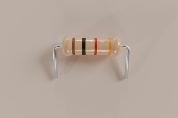
A standard 4-band 10k resistor is brown, black, orange, followed by the tolerance band. Brown and black give 1 and 0; orange multiplies by 1,000, producing 10,000 Ω. Gold makes the complete code brown-black-orange-gold for ±5%.
A 5-band 10k ohm resistor is commonly brown-black-black-red, followed by tolerance. The first three bands form 100 and red multiplies by 100, again producing 10,000 Ω. Brown as the fifth band indicates ±1%. When band spacing or colors are unclear, measure the resistor out of circuit because parallel PCB paths can lower an in-circuit reading.
Why 10 kΩ Works Well in Analog Design
A 10k resistor often provides a practical balance between current consumption, thermal noise, input bias-current error, and interaction with parasitic capacitance. The 10k resistor is not an automatic optimum, but it is a sensible starting range for many op-amp bias networks, voltage dividers, transistor bias paths, and RC filters.
Voltage dividers: Two equal 10 kΩ resistors divide an unloaded 3.3 V rail to 1.65 V. The divider draws 165 μA, and its Thevenin resistance is 5 kΩ, so the following input must have sufficiently low leakage and high impedance.
RC timing and filtering: A 10k resistor with 100 nF gives a 1 ms time constant. As a first-order low-pass filter, the pair has a cutoff near 159 Hz; capacitor tolerance and the driven node's impedance shift the real value.
Op-amp error control: Input bias current flowing through 10 kΩ creates an offset. For example, 50 nA produces 0.5 mV, which may be acceptable for a sensor threshold but not for a precision measurement channel.
Before releasing the layout, calculate worst-case output with resistor tolerance and input leakage, then keep high-impedance nodes short and clean. That analysis matters more than selecting the 10k resistor because it appears in a reference design.
USB Connection Troubleshooting
A 10k resistor can support USB control circuitry, but the 10k resistor is not a universal USB termination or identification value. In a USB-C sink, each CC pin normally needs its specified Rd value, commonly 5.1 kΩ; using 10 kΩ can prevent reliable attach detection. Legacy USB full-speed and low-speed pull-up functions commonly use 1.5 kΩ, so a 10k ohm resistor is not a substitute there either.
Start with the schematic role. Trace every 10k resistor near the connector. Classify it as a pull-up, pull-down, divider, discharge path, MOSFET gate bias, reset bias, or enable bias. Compare the value with the USB controller and connector requirements, not with nearby parts.
Inspect the unpowered board. Check the fitted marking or reel record, solder joints, tombstoning, and continuity to the intended net. Measure resistance only after capacitors discharge; lift one terminal when parallel paths make the result ambiguous.
Verify power and state pins. During plug-in, measure VBUS, local rails, reset, enable, fault, and overcurrent signals. A missing 10k resistor or solder bridge can hold a pin between valid logic levels even when D+ and D? routing is correct.
Check attach before data. For USB-C, confirm CC voltage behavior and orientation on both CC pins. For USB 2.0 data, use an oscilloscope with appropriate probing to check pull-up presence, reset signaling, and excessive loading; do not diagnose high-speed integrity with a handheld meter.
Separate design from assembly. If one board fails, compare it with a known-good board. If every board fails, review value selection, footprint mapping, ESD-device leakage, connector pinout, reference planes, differential-pair routing, and firmware configuration.
How to Use a Resistor Color Code Calculator
A resistor color code calculator is reliable only when the band count and reading direction are correct. Use it as a decoding aid, then verify the result against the schematic and a meter when the part affects startup, protection, or communication.
Count the bands. Choose four bands for two significant digits or five bands for three significant digits.
Set the reading direction. Place the tolerance band last. Wider spacing before the final band is a useful clue.
Enter each color in order. Brown-black-orange-gold returns 10 kΩ ±5%. Brown-black-black-red-brown returns 10 kΩ ±1%.
Check the expected range. A ±1% 10k resistor should be between 9.9 kΩ and 10.1 kΩ at its specified reference conditions. Meter accuracy, test leads, temperature, and parallel PCB paths affect the reading.
10k Resistor Applications on a PCB
The best 10k resistor applications are low-current nodes where 10 kΩ meets a calculated bias, timing, or impedance target. Use a 10k resistor only after checking the real node conditions. Common examples include the following.
Reset and enable pins: A pull-up or pull-down gives the pin a defined state during power-up, before firmware configures the MCU.
Sensor interfaces: A 10k resistor can form a divider with an NTC thermistor, limit current into a protected input, or set an amplifier's gain with another resistor.
Transistor and MOSFET control: A 10 kΩ base or gate bias can keep a switch off when its driver is high impedance, provided switching speed and leakage remain acceptable.
LED and power circuits: A 10k ohm resistor is useful for indicator-transistor bias, feedback, or discharge sensing, but it usually passes too little current to drive an LED directly at normal brightness.
Digital Interfaces and Pull Up or Pull Down Design
A 10k ohm resistor is suitable as a digital pull-up or pull-down when it guarantees valid logic levels within the required rise time and leakage budget. For a static input, check the worst-case leakage from the IC, protection network, connector, and contamination against the input thresholds.
For a pulled-up bus, resistance and total capacitance set the rising edge. With 10 kΩ and 100 pF, the RC time constant is 1 μs and the approximate 30%–70% rise time is 0.847 μs. That may be acceptable for a button or interrupt line, but it is too slow for many 400 kHz I2C designs, where a lower pull-up value is often required after checking sink current.
A useful review sequence is: calculate pull current at the active level, calculate the worst-case idle voltage from leakage, estimate the RC rise time, and validate it on the assembled PCB. Use one 10k resistor per required net unless the circuit deliberately shares a pull; hidden parallel pulls change both current and timing.
Frequently Asked Questions
What does 10k mean on a resistor
It means the nominal resistance is 10 kilohms, or 10,000 Ω. The actual value stays within the stated tolerance at the specified reference conditions.
Can I replace a 10k resistor with another value
Only after checking the circuit function and worst-case limits. A nearby value may change divider voltage, bias current, RC timing, logic margin, or power dissipation even when the board still appears to work.
Does resistor orientation matter on a PCB
No, a standard fixed resistor is non-polarized. Consistent orientation can still improve inspection and make markings easier to read during assembly troubleshooting.
Is a 10k ohm resistor suitable for I2C pull ups
Sometimes, especially at low speed and low bus capacitance. Calculate the rise time and verify it on the real PCB; 10 kΩ often becomes too weak as bus capacitance or clock rate increases.
How do I test a 10k resistor on an assembled PCB
Power the board off, discharge capacitors, and measure across the part. If the result is below the expected range, parallel circuit paths may be responsible; lift one terminal or compare with the schematic before declaring the 10k resistor faulty.